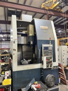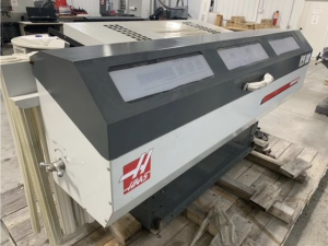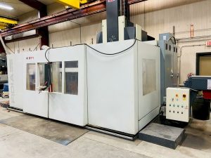
Technical Evaluation Guide: How to Identify a Quality Used, Secondhand, Pre-Owned, Surplus EQUIPTOP EMV 1100 CNC Vertical Machining Center made in Taiwan
0. Gather reference data: “what is the EMV-1100 supposed to be”
Before inspection, you want to have a baseline of what the machine is (standard features, specs, common options). For the EMV-1100, based on Equiptop’s published data (and similar models in the EMV linear-way series):
- The EMV-1100 is part of Equiptop’s linear-way CNC VMC lineup.
- Typical features (standard or optional) include:
• Auto lubrication system for linear ways and screws
• Floating drawbar mechanism (so that unclamping forces are not transmitted to spindle bearings)
• Full enclosed guard, chip auger, washdown system, Z-axis brake, portable flush gun, leveling blocks & screws, etc.
• Laser compensation or measurement of full travel stroke to maintain motion accuracy (i.e. calibration / compensation built into machine)
• Optional high-precision linear guideways (wide blocks) for wear resistance
• Tool magazine / ATC options (e.g. a 16-station armless ATC type) - The manufacturer cautions that specifications can change (i.e. published numbers are for reference).
Thus, when you inspect a unit, you should verify which of these features it actually has (standard or retrofitted) and whether they are functional.
1. Preliminary / documentary checks (before physical inspection)
Before walking into the facility, ask for or verify:
| Check | Why it matters | What to request / examine |
|---|---|---|
| Machine history & logs | Machines with documented maintenance and repair history typically indicate better care | Ask for maintenance logs, repair records, spindle rebuilds, service intervals, replacement components, lubrication schedules |
| Total power-on & cutting hours | Wear largely depends on how much the machine has been used, especially under load | Ask for machine hours, spindle hours, cutting hours vs idle hours |
| Operating context | The materials processed (e.g. hard alloys, abrasive materials) and environment (coolant type, dust, chips) influence wear | Ask what parts or materials were regularly run, whether coolant was properly maintained, how the shop handled chips and coolant filtration |
| Original documentation | Schematics, parts lists, manuals, calibration reports help for future maintenance or repair | Request original electrical, hydraulic, pneumatic, and mechanical drawings; control manuals; wiring; parts catalogs |
| Modifications / upgrades | Some machines have aftermarket upgrades (e.g. control replacement, spindle upgrade, additional sensors) which may be beneficial or problematic | Ask for details of retrofits, who performed them, documentation, and whether they conform to good engineering practices |
| Spare parts, tooling, accessories included | The seller may or may not include tooling, fixtures, spare parts, probes, etc. | Get a list or inventory of what is included (collets, tool holders, probe, fixtures, coolants, etc.) |
If possible, condition acceptance or a test run in your purchase contract is wise.
2. Visual & structural inspection
Once at the site, thoroughly walk around the machine, visually inspect surfaces, and look for signs of neglect, damage, or modifications.
Exterior / frame / enclosure
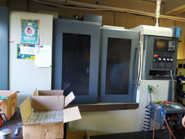
- Enclosure, guards, doors, windows
Ensure that all guards and doors close cleanly, interlocks (if any) are functional, and windows (if present) are intact. Missing panels, bent doors, or broken interlock switches may indicate rough use or bypassing of safety. - Chip coverage, coolant residue, cleanliness
A machine encrusted with chips, sludge, or dried coolant is a warning sign that maintenance was neglected. Excessive build-up in hidden parts may hide damage. - Rust, corrosion, pitting
Check exposed metal surfaces, corners, edges, covers, door frames, and under trays for rust or corrosion. Surface rust is repairable; deep pitting near ways or mounts is more serious. - Weld repairs or crack patches
Look for visual evidence of welds or repairs on the base, column, saddle, or table — particularly around high-stress areas. If you see grinding or filler, it may have been damaged in the past. - Leveling and foundation condition
The machine’s base and foundation should be well preserved. Disturbed leveling blocks, missing grout, or signs of settlement or shifting are red flags.
Table, work surfaces, mounts
- Table top & T-slots
Inspect the table surface for dents, gouges, wear, distortion, or evidence of heavy impact. Check T-slots for wear, rounding, or distortion. - Mounting surfaces / fixture interfaces
The areas where the work holding or fixture attaches should be clean, without deformation or scoring. - Flatness & warpage tests
Use a precision straightedge or granite reference block and a dial indicator to check for flatness and twist across the table.
3. Kinematic systems: axes, guides, feedscrews
This section is critical — many machines fail or degrade due to worn guideways or screws.
Guideways / linear ways / slides
- Visual examination
Look carefully at linear guide rails (if installed) or box-way surfaces for scoring, scuffs, corrosion, pitting, or wear strips showing metal contact. - Feel / manual motion
With power off (and machine safe), manually jog or slowly move each axis (X, Y, Z) and observe resistance, smoothness, or sticking. Any zones of “hardness,” binding, or jerky motion are concerning. - Backlash / play measurement
Use a dial indicator or appropriate test method to measure backlash in each axis. Compare to acceptable tolerances (dependent on machine class). Excessive backlash indicates wear in screw or nut, or in servo/drive coupling. - Straightness / deviation along travel
If possible, mount a test bar or use a precision measurement system (laser, indicator, or ball bar) to check how straight the axes travel over full traverse. - Preload or clearance checks
Some guide systems have adjustable preload. Verify the preload (if any) is still within spec.
Ball screws / lead screws / feed screws
- End play & axial movement
Lock the carriage and push/pull the screw axially to detect loose bearings, nut wear, or looseness in couplings. - Torque uniformity / smoothness
Slowly drive the axis through full travel under low load to sense any variation in torque (drag, sticking, uneven resistance). - Screw thread wear / scoring
Inspect visually for wear, scratches, or corrosion on the screw shaft, especially near supports or transitions. - Lubrication condition
Check that screws and nuts are being supplied with proper lubricant (oil, grease) and that the lubrication path is clean (no clogging, contamination).
Drives, motors, couplings
- Servo motor inspections
Check for any signs of overheating, discoloration, cracked housings, loose connectors, or vibration when running. - Couplings / torque transmission
If the screw-to-motor coupling is accessible, inspect for play, wear, or looseness. Flexible couplings may degrade over time. - Limit switches, homing sensors, encoders
Cycle axes to their home or limit positions and observe whether sensors trigger properly and reliably. Misalignment or false trips are trouble.
4. Spindle & tooling interface
Because the spindle is one of the most expensive components to repair or replace, thorough testing is vital.
- No-load run across speed range
Power up the spindle (without load) and run it through low, mid, and high speeds. Listen and feel for unusual vibration, hum, noise, or imbalance. Excessive heating is also a concern. - Runout / radial & axial error
Use a precision test bar or dial indicator to check runout (radial) at multiple points along the spindle and the taper. Also check axial end play. Compare to acceptable tolerances. - Bearing noise / condition
While running, use a stethoscope or vibration meter to hear if there is rumble, grinding, or resonance indicative of bearing wear. - Thermal drift / growth
After running the spindle or cutting for an extended period, measure any drift or growth in the spindle’s position relative to the work surface. Check whether any thermal compensation or alignment system (if built in) is functioning. - Taper wear, fretting, pitting
Visually inspect the tool holder taper (e.g. BT/CT, etc.) for fretting, corrosion, pitting, or wear. These degrade the repeatability and concentricity of tooling. - Drawbar and clamping mechanism
Test the drawbar mechanism and check that clamping / unclamping works reliably and uniformly. Any binding, slippage, or erratic clamping force is problematic. - Through-spindle coolant / high-pressure coolant lines
If the EMV-1100 is outfitted with coolant-through spindle or high-pressure coolant (if applicable), test flow rate, pressure, and check internal lines for leakage or clogging. - Vibration signature
If you have access to a vibration analyzer, run the spindle at operating speeds and check for any abnormal frequency signatures or amplitudes.
5. Control, electronics, software & diagnostics
Even a mechanically sound machine is of limited use if controls or electronics are failing or obsolete.
- Boot-up & interface
Power on the machine and observe whether the CNC control boots cleanly, without errors. Inspect display, keypads, indicators, alarms. - Axis movement under control
Use the control to jog each axis, move at different feed rates, test commands, and verify that the motion is smooth, responsive, and free of stutter or delay. - Loading / executing programs
Load a sample G-code or part program and execute it. Confirm that commands, tool changes, offsets, coordinate systems, macros, etc. all work. - Error / alarm logs
Inspect the control’s error history, alarms, or maintenance logs. Repeated or unresolved errors may indicate persistent or latent issues. - Backups / memory / media
Check whether CNC programs, parameter backups, and configuration files are accessible, intact, and retrievable. - Probing / measurement / optional sensors
If the machine has probes or measurement systems, test probing cycles, calibration, compensation routines, and accuracy of feedback. - Wiring, connectors, conduit, cable carriers
Open the control cabinet and wiring trays to check for signs of overheating, burnt insulation, loose connectors, frayed cables, or moisture ingress. - Cooling / ventilation of control cabinet
Ensure fans, filters, vents, or heat exchangers are present, functional, and well maintained. Overheating is a common source of failure. - Electrical power quality & stability
If possible, measure voltage, phase balance, grounding, noise, and ripple. Poor incoming power may have stressed the machine’s electronics during its life.
6. Auxiliary & supporting systems
Many problems arise not from the core axes/spindle, but from auxiliary systems.
- Coolant system
Inspect coolant tank(s), pumps, filters, piping, valves. Check for leaks, pump noise, contamination, filter condition, coolant condition (cleanliness, concentration). - Chip / swarf handling
Run the chip auger / conveyor (if present) and inspect its motion, condition, and whether it is in proper alignment, free from jamming or wear. - Air blow / pneumatic systems
Test blow-off nozzles, air guns, pneumatic valves, air filters, regulation, condition of hoses, and proper functioning. - Lubrication / auto-oiling systems
The linear ways, screws, and other parts often rely on automated lubrication. Inspect that the lubrication system is functioning (pumps, lines, metering, no blockages). - Hydraulic systems (if present)
If the machine uses hydraulics (for tool clamping, coolant valves, etc.), check for leaks, pressure stability, reservoir condition, oil cleanliness, and responsive operation. - Electrical cabinet / panel
The interior of the control cabinet and power panels should be clean, dry, well organized, labeled, and show no signs of overheat, corrosion, or loose wiring. - Safety systems / interlocks
Test emergency stops (E-stop), door interlock switches, limit interlocks, protective covers, and any sensors or safety hardware to confirm they are functional. - Auxiliary accessories
Check whether included accessories such as tool setters, probes, fixtures, coolant chiller, fume collectors, chip conveyors, fixture kits, etc., are present and functional.
7. Alignment, geometry, calibration & test cutting
After verifying mechanical and electronic health, the ultimate proof is in how the machine performs under real or test cutting / motion.
- Leveling & stability
Confirm that the machine is correctly leveled and well supported. If previously moved, ascertain that the foundation, base, or anchoring is still stable. - Orthogonality / squareness
Use precision measurement tools (e.g. granite block, dial indicators, test bars) to check that X–Y, Y–Z, and X–Z axes remain orthogonal (within acceptable tolerances). - Tramming / spindle perpendicular to table
Verify that the spindle axis is perpendicular (or within spec) to the table surface by tram tests using indicators or calibration bars. - Linearity / axis straightness
Using a calibrated test bar or linear referencing instrument (laser, interferometer, etc.), check each axis for deviations / error across the full travel. - Circular interpolation / volumetric error / ball bar test
If you have access to a ball bar or 3D volumetric measurement system, run circular, helical, or contour tests across the working envelope to examine the combined machine error. - Repeatability / repositioning tests
Command the same point repeatedly (e.g. move to X = 100 mm, retract, return) and measure the deviation. This tests backlash, servo accuracy, and repeatability. - Test cuts / benchmark parts
If possible, run a real test part using shop-relevant cutting parameters and measure critical dimensions (tolerances, surface finish, flatness, parallelism). Try cuts at near, mid, and far regions of each axis travel. - Thermal stability / drift test
Run a longer cycle under load, let the machine stabilize thermally, and then re-measure critical points to check for drift or deformation under heat.
8. Risk assessment, thresholds & negotiation strategy
Once you gather observations, use this section to decide whether the machine is a worthwhile purchase and how to price/structure your offer.
- Deal-breakers (serious red flags)
• Spindle bearing failure, excessive runout, severe vibration
• Major structural damage (cracks, distortion, welded repairs in critical areas)
• Control system unrecoverable, missing, or obsolete beyond repair
• Massive unknown modifications or missing parts/documentation - High-risk (repairable but costly)
• Excessive wear in screws or linear ways (high backlash, non-smooth travel)
• Faulty lubrication systems or auxiliary systems in disrepair
• Worn or damaged tool-holding interface
• Electrical problems, overheating, or inconsistent control behavior - Acceptable / manageable issues
• Cosmetic wear, surface rust, missing covers (if restorable)
• Minor misalignment or drift (if within repairable tolerance)
• Missing non-critical accessories (fixtures, tooling) - Positive indicators
• Clean, well-documented maintenance history, with original manuals
• Smooth motion, minimal backlash, repeatability tests OK
• Spindle in good health, stable under test cuts
• Functional controls, responsive axes, clean electronics
• Included tooling, fixtures, probes, spares - Pricing strategy & offer structure
• Include allowances in your offer for refurbishment, calibration, spare parts
• Make conditional acceptance contingent on final in-situ inspection or test cutting
• Negotiate based on cost to bring the machine up to fully functional state
• Consider risk premium for older machines or units with missing documentation