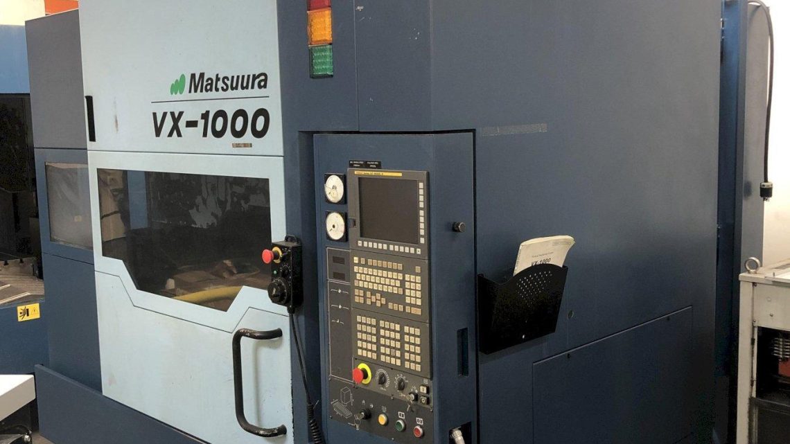
Technical Evaluation Guide: How to Identify a Quality Used, Secondhand, Pre-Owned, Surplus Matsuura VX-1000 CNC VMC Vertical Machining Center made in Japan
1. Know the baseline specifications & configurations
Before you walk into a shop or inspect a listing, you should know what the VX-1000 is supposed to be, its standard features, and common options. That way, deviations or red flags can stand out.
Here are key specs & features (from Matsuura and third-party sources):
- Travel (X / Y / Z): 1,020 / 610 / 610 mm (≈ 40.15″ × 24.01″ × 24.01″)
- Table size: 1,200 × 600 mm (≈ 47.24″ × 23.62″)
- Load capacity: 500 kg (≈ 1,100 lb)
- Spindle: Standard 15,000 rpm with BT/CT #40 taper; optional 20,000 rpm upgrade in many units (especially newer ones)
- Spindle motor/torque: AC 15/22 kW (low & high speed windings) is typical.
- Tool magazine: usually 30-station drum as standard; optional expansions (48, 60) in many machines.
- Standard features: lift-up chip conveyor (scraper type), spiral chip conveyor, high-pressure through-spindle coolant (2 MPa), thermal displacement compensation, etc.
- Control systems commonly seen: Fanuc 31i series (or equivalents) in many modern VX-1000s.
Knowing those “as built” parameters helps you spot if a claimed “VX-1000” is really one, or has been heavily modified, or mis-described.
2. Pre-inspection: documentation, history & context
Before even stepping into the plant:
- Maintenance / repair logs: Ask for the full service history (dates, parts, failures, rebuilds). Machines that have been well documented tend to be more trustworthy.
- Power-on / cutting hours: Understand both “hours on the machine” and “hours under load / cutting time.” A machine may have many idle hours but low cutting hours (less wear).
- Operator / maintenance interviews: Ask the people who ran or serviced it:
• What materials were machined (abrasive, hard, messy, etc.)?
• Any recurring or chronic faults?
• Any major repairs or spindle changes?
• Was coolant / chip management properly done (coolant change, cleaning) or was it neglected? - Original manuals, drawings, spare parts lists: Having full documentation (as-built drawings, wiring diagrams, service manuals) is a big plus.
- Modifications, retrofits, upgrades: Has the machine been upgraded (spindle to 20k, additional control features, tool changer changes, etc.)? Are such modifications professionally done?
These front-end checks help you prepare expectations and avoid surprises.
3. Visual & structural inspection
Once you’re physically in front of the machine, do a methodical walkaround. Many problems (or signs of neglect) are visible.
Structural / frame / exterior
- Cracks, warpage, weld repairs: Look across the column, base, saddle, and table mounting surfaces for any crack lines, repaired welds, or localized distortion.
- Rust or oxidation: On surfaces, corners, enclosures, ways, etc. Excessive rust may indicate long idle periods or poor environmental control.
- Missing covers, panels, shrouds: Gaps, removed panels, or dangling wiring are red flags that someone may have disassembled or bypassed safety.
- Guarding, doors, windows: The enclosure doors should close cleanly and lock. Windows should be intact and secure.
- Chip coverage / cleanliness: A machine heavily caked with chips or coolant residue often indicates poor maintenance.
Bed, table, mounts
- Table flatness, condition of T-slots: Check for wear, gouging, deformation in the table surface and T-slots.
- Clamping surfaces, base interface surfaces: The surfaces where fixtures mount should be clean, flat, and undamaged.
- Anchoring / foundation condition: If bolted or anchored, see how well the base has been supported, whether there were settlement issues, and whether leveling shims or grout have been disturbed.
4. Mechanical motion & kinematic systems
This is where you verify the “moving parts” integrity. Many older machines fail because of worn guides, screws, or inadequate lubrication.
Guideways / ways / slides
- Visual inspection: Look for scoring, pitting, wear marks, rust, or damage on linear guide surfaces or conventional box ways.
- Manual motion test (power-off jog or manual crank): Move each axis slowly, feel for stick-slip, binding, nonuniform resistance, or “flat spots.”
- Backlash / play measurement: Use test indicators or standard inspection procedures to measure backlash in each axis. Excessive backlash is a warning.
- Parallelism / straightness: Use an alignment test (e.g., with a test bar, dial gauges, or CMM) to check that axes stay straight over travel.
Ball screws / lead screws / feedscrews
- End play / axial backlash: With the axis static, try to wiggle the screw axially to detect loose bearings or unions.
- Smoothness / uniform torque: Rotate manually or via slow feed to feel for rough patches, drag, or torque variation along the travel.
- Lubrication condition: Check that the screws are lubricated properly, not dry or contaminated.
Drives & motors
- Servo motors / drives: Inspect motor housings, cables, connectors. Listen (when powered) for unusual humming, vibration, or temperature rise.
- Couplings / belts / transmission elements: If any belts or couplings exist (less common in direct-drive machines), check for wear, slack, cracks.
- Limit switches / homing sensors: Cycle axes to ensure limit sensing works correctly and without false trips.
5. Spindle & tooling interface
The spindle is often the most expensive and delicate component. Its condition is critical.
- No-load run test: Run the spindle across speed ranges (from low speed up to maximum) and listen/feel for noise, vibration, unusual heating, or imbalance.
- Runout / axial/traveling accuracy: Use a precision test bar or dial indicator to measure runout at various points. Verify radial error and angular error.
- Bearing condition: Listen for rumble, grinding, or abnormal resonance. Use a stethoscope or vibration meter if available.
- Thermal drift: In longer runs, check how much the spindle warms and whether its growth causes shift. If thermal compensation is present, see if it is functioning.
- Tool holding / taper wear: Check the taper (BT/CT #40) for wear, fretting, or damage. Also inspect tool holders, drawbar, retention mechanisms.
- Through-spindle coolant (TSC/HPCC): If the machine has through-spindle coolant, test the pressure and flow, check internal coolant lines for blockage or leakage.
6. Control system, software & electronics
Even a mechanically excellent machine is of little use if the CNC control and electronics are failing or obsolete.
- Power-up test & interface check: Turn on the machine, check whether the control boots properly, display integrity (LCD, indicators), keypads, emergency stops, etc.
- Axis movement under control: Jog axes through the control interface; test interpolated movements, look for “jerkiness” or delays.
- Program loading & execution: Load a sample G-code or test program; observe whether it runs accurately. Test basic routines, tool change commands, coordinate offsets, etc.
- Error / alarm history: Inspect the CNC error logs or alarm history—frequent recurring alarms may point to chronic issues.
- Backups, program storage media: Confirm there is a working program backup (memory, USB, PC link).
- Interface with external systems (probes, tool setters, auto-measurement): If the machine is fitted with probe systems (Renishaw, etc.), test their operation (probe cycles, calibration).
- Wiring, connectors, cable management: Open panels to inspect for burnt wires, loose connectors, grounding, cable wear, cable carriers, etc.
- Power supply / control cabinet cooling: Ensure that fans, vents, filters are present, clean, and functional; check for signs of overheating or water ingress.
7. Test machining & accuracy validation
This is perhaps the best “proof in the pudding” check—if you can see the machine produce parts to spec, your confidence goes way up.
- Benchmark test piece: Run a known test part (for example, a precision block, a calibration cube, or a standard interference fit test) and measure dimensions and tolerances.
- Corner points / extremes of travel: Run test cuts at multiple locations across the travel of each axis (near origin, mid, near limits) to check for consistency.
- Contour / interpolation tests: If you intend to use more advanced movements, test circular interpolation, helical moves, or contouring to see how smooth the motion is under command.
- Tool change & indexing tests: Execute several tool changes to verify the ATC is precise, repeatable, and error-free. Also check tool-change cycling time.
- Repeatability / repositioning test: Command the same point multiple times and measure deviation (e.g. “move to X, then away, then back” and measure shift).
- Thermal stability test: Run a longer cycle at high cutting load and then re-measure key dimensions to see if drift occurs.
Use precision metrology tools (gage blocks, micrometers, dial indicators, CMM if available) to validate results.
8. Auxiliary systems & machine support features
Many failures or deficiencies come from supporting systems, not the core spindle + axes. Make sure these are also in good shape.
- Coolant system: Inspect coolant tank, pumps, filters, coolant quality, piping, valves, leaks, and cleanliness.
- Chip management / conveyors / augers: Run the chip conveyor, check for blockage, wear, proper motion. Augers or spiral conveyors should run smoothly.
- Air / blow-off, dryers, mist / lubrication systems: Test pneumatic blow-offs, air nozzles, mist collectors, central lubrication.
- Hydraulics (if applicable): If the machine has hydraulic systems (clamping, coolant valves, etc.), inspect for leaks, stability of pressure, reservoir condition.
- Electrical panel / cabinet: Look for cleanliness (no dust, chips), proper labeling, good cable routing, cooling, and protection.
- Safety systems / interlocks: Verify emergency stops, safety doors, interlocks, guards, light curtains (if any) all function reliably.
- Spare parts, tooling, accessories: Check what is included (tooling, workholding vises, fixing kits, extra parts, tools, probes). Often a seller omits them.
9. Alignment, leveling, geometric checks
Once the machine is set up in its current position, you should verify its geometric accuracy and alignment.
- Leveling / base flatness: Check the machine is properly leveled and that the base or anchor points remain stable.
- Squareness & orthogonality: Verify that X–Y, Y–Z, and X–Z axes are orthogonal (right angles) within spec.
- Tram (spindle perpendicular to table): Measure whether the spindle axis is perpendicular to the table surface.
- Axis linearity: Use a calibrated test bar or straight-edge to test each axis’ linearity over full travel.
- Volumetric performance / VDI tests: If possible, perform volumetric error testing that assesses combined machine errors across the working volume (requires more advanced measurement equipment).
10. Risk assessment & decision matrix
Finally, integrate all your findings into a risk-based decision:
- Major red flags (deal-breakers):
• Spindle with unacceptable runout or noise (indicates bearing failure)
• Severe or unrepairable damage to structural parts
• Control system failure or missing/obsolete control parts
• Repeated chronic defects or missing documentation - Moderate issues (repairable but need factoring):
• Excessive backlash or wear on screws/ways
• Need for retrofitting or replacement of auxiliary systems
• Cosmetic issues, surface rust, missing covers - Positive indicators:
• Clean, well-documented, stable service history
• Ability to produce parts within tolerances during test cuts
• Good spindle health and minimal vibration
• Complete set of manuals, tooling, probes, spares
Make sure to place contingencies in your purchase offer to allow for further inspection after acceptance, and possibly include a clause for adjustment if hidden defects arise.