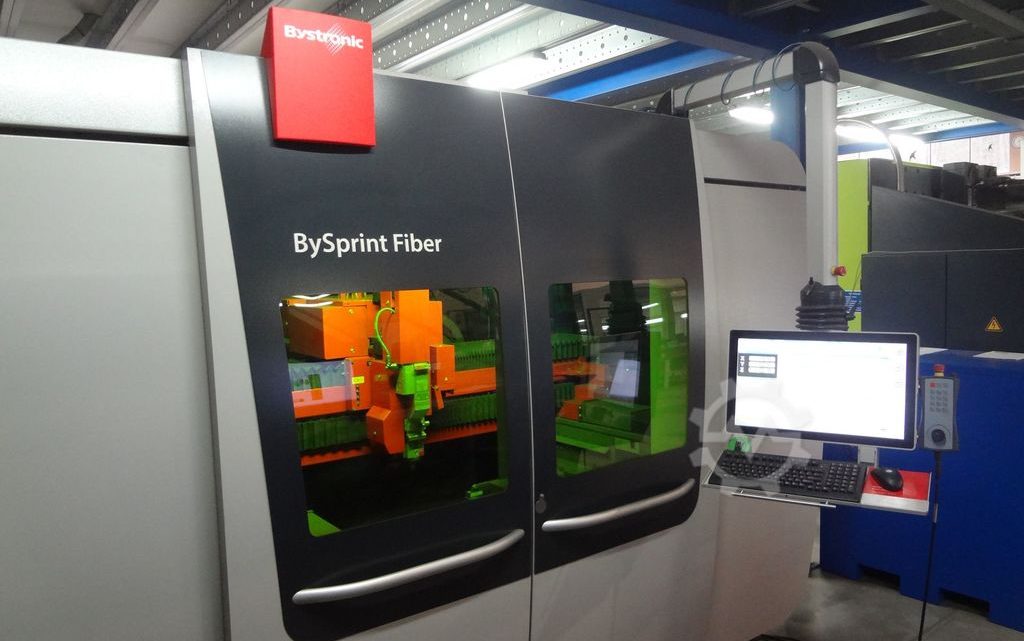
Technical Buyer’s Handbook: Assessing Pre-Owned , Used , Secondhand, Surplus CNC Machines Before Purchase Bystronic BySprint Fiber 3×1,5m CNC Laser made in Switzerland
Below is a Technical Buyer’s Handbook / Due-Diligence Checklist for evaluating a pre-owned / used / surplus Bystronic BySprint Fiber fiber-laser cutting machine (for example, sheet size ~ 3 × 1.5 m variant), “Swiss made / From Switzerland” origin. Use this as a structured guide; adapt tolerances, subsystems, and weighting to your production needs and budget.
1. Reference / Benchmark Specifications (BySprint Fiber Series)
Before inspection, you should collect the nominal (as-new) technical specifications for the particular variant you are evaluating. That gives you a benchmark to compare against. Some published specs for BySprint Fiber series include:
- The BySprint Fiber 3015 variant is noted as “built in Switzerland” in used machinery listings.
- The BySprint Fiber family datasheet shows specifications: positioning accuracy ± 0.1 mm, repeatability ± 0.05 mm over a 1 m measuring length (VDI/DGQ 3441)
- For the Fiber 3015 variant: cutting area 3,048 × 1,524 mm, Z travel ~ 70 mm.
- Maximum workpiece weight for 3015: ~ 890 kg (for that size).
- The maximum positioning speed (simultaneous) is ~ 140 m/min (for many variants in the series)
- The machine weights are substantial—e.g. the 3015 version is ~12,000–13,000 kg (without exhaust / auxiliary units) in used listings
These specs help you decide whether the used machine is close to expected performance or has drifted too far.
2. Pre-Inspection / Remote Phase
Do as much groundwork as possible before visiting the site:
- Request documentation
- Original mechanical / electrical / optical / control manuals
- Wiring diagrams, layout prints, optical path, beam delivery schematics
- CNC / control (ByVision or other) parameter backups, software versions
- Maintenance / service logs (laser source, chiller, optics, mirrors, alignment)
- Calibration / alignment certificates (optical path alignment, beam axis, focusing)
- History of parts replaced (fiber source, optics, galvanometer mirrors, axes motors)
- Any modification or upgrade history (e.g. higher power source, multi-head, automation) - Photos & videos
Request high-resolution images/videos of:
– Machine frame, gantry, bridges, supports
– Laser source / fiber module, cooling, converters
– Beam path (mirrors, beam delivery modules)
– Cutting head, nozzle, focusing optics
– Linear axes (rails, carriages), drive systems
– Electrical / control cabinets, wiring, connectors
– Motion videos if machine still operational (axis move, laser firing, cut) - Ask key diagnostic questions
- Year of manufacture, hours of use / laser on time
- Reason for selling / decommission
- Is the machine currently operational and under power?
- Which major subsystems have been repaired / replaced (laser source, optics, alignment mechanisms)?
- Are spares (optics, mirrors, nozzles) included?
- What control / interface version is installed?
- Was the machine used primarily on thick or thin materials, what frequency of usage? - Prepare measurement & test tools
Bring or plan for:
– Dial indicators, micrometers, straight edges
– Laser alignment tool / beam path alignment tools, optical meters
– Power meters / current sensors
– Thermography camera (for hot spots)
– Vibration sensor / accelerometer
– Tools for opening covers, optical path inspection - Logistical planning
- Evaluate machine footprint, ceiling height, crane / rigging access
- Estimate weight and plan lifting points
- Plan for utilities: power, cooling (chiller), compressed air, exhaust, gas supply (O₂, N₂)
- Foundation and floor flatness / vibration isolation requirements
3. Visual & Structural / Static Inspection (Power-Off)
Start with an in-depth walk-around before powering anything.
3.1 Machine Frame, Bridge, Gantry & Support Structure
- Inspect the main frame, gantry beams, columns, supports for cracks, weld repairs, distortion, bending
- Check for signs of alignment rework, shimming, or regrinding of guide surfaces
- Look for corrosion, rust spots, pitting, especially near coolant, exhaust, or floor contact areas
- Check way covers, protective covers, sealed sections, guards for damage or missing parts
- Inspect beam guides / rails for visible wear, dents, or debris accumulation
- Check that all fasteners, anchoring plates, shims are intact and not loose
3.2 Linear Axes, Guides & Carriages
- Examine linear guide rails, bearings, carriages for wear, scoring, lubrication condition
- Inspect rails for spalling, chips or pitting
- Check the motion of carriages (if manual push is allowed) for binding or uneven movement
- Check for play / looseness in axes mechanically
- Examine the drive mechanism (rack & pinion, ball screw, direct drive) for signs of wear, backlash, lubrication issues
- Verify lubrication / grease / oil supply lines are intact and not clogged
3.3 Laser Source, Fiber / Module, Beam Path Infrastructure
- Inspect the laser module or fiber delivery unit: housing, connectors, cooling lines
- Check fiber cables (if external), connectors, strain reliefs for wear or damage
- Inspect beam mirrors, mirror mounts, optical path enclosures for cleanliness, misalignment, damage
- Inspect the cutting head, focusing optics, nozzle, and protective windows for wear, deposits, damage
- Look for signs of contamination, smoke trails, carbon deposits near the head
3.4 Optical & Mirror Components, Beam Path Enclosures
- Inspect protective enclosures for mirrors, beam path tubes, shielding
- Open covers (if allowed) and visually inspect mirror surfaces for scratches, pitting, coating degradation
- Check that mirror mounts are rigid and adjustable, no signs of looseness
- Inspect alignment adjustment mechanisms (micrometers, fine screws) for freedom of motion and no binding
3.5 Electrical Cabinets & Wiring
- Open main control / drive cabinets and inspect internal condition: dust, moisture, corrosion, overheating traces
- Look for discolored wires, melted insulation, burned terminals
- Inspect drive modules, power supply, control boards, I/O modules
- Check cooling fans, filters, ventilation paths, dust build-up
- Inspect wiring bundles, connectors, shielding, strain reliefs
- Check power cabling to the fiber/laser, cooling pumps, exhaust system
3.6 Safety & Interlocks
- Verify existence and mechanical integrity of emergency stop (E-stop) buttons
- Inspect safety interlock switches, door sensors, enclosure safety systems
- Confirm protective enclosures over the laser cutting area are intact and not bypassed
- Inspect light curtains (if present), beam safety shielding, access doors and locks
4. Power-Up & Functional / Dynamic Testing
With safety measures in place, proceed to power up and run dynamic tests. Use the seller’s cooperation and ensure safety protocols.
4.1 Initial Control & System Diagnostics
- Power on the CNC / control system (ByVision or variant), observe boot sequence and logs
- Check for persistent alarms or errors
- Verify parameter loading, fiber module readiness, I/O status, sensor statuses
4.2 Axis Movements & Motion Tests
- Jog X, Y, Z axes at low speed: check smoothness, direction, no binding or stiction
- Execute full traverse motions (within safe range) to inspect for irregular motion, jerk, vibration
- Command known moves (e.g. 100 mm, 200 mm) and measure with a dial indicator or gauge to test linear accuracy
- Reverse directions and check for backlash or dead-band
- Run simultaneous X + Y motion (diagonal paths) to test coordination and linear cross-coupling
4.3 Laser / Beam Firing & Cut Simulation (if permitted)
- Conduct test firing of the laser (at low power) to inspect beam alignment, focus stability, head response
- If safe, run a light test cut (thin plate) to verify cut quality, kerf, accuracy, edge quality
- Monitor the entire path—beam travel, acceleration, deceleration, head response
- Check restartability: pause the cut / path and resume, see if alignment holds
4.4 Thermal Stability / Drift Tests
- Let the machine run for an extended period (30–60 min) with motion cycles or idle to warm up
- After warm-up, re-check key dimension moves, reference points, alignment to detect drift
- Monitor temperatures in drives, laser module, cooling systems
- Use thermal imaging to detect hot spots or overheating components
4.5 Safety & Fault Behavior Tests
- Trigger emergency stop during motion or beam firing to verify immediate safe shutdown
- Hit limit switches or home switches to confirm axes stop or retract as expected
- Simulate sensor or interlock failure (if safe to do) to test error handling
- Test door / lid interlocks during operation
4.6 Endurance / Repetition / Cycling Test
- Run multiple cycles: e.g. repeated positioning, motion, beam firing or mock cut patterns
- Observe any progressive deviation, drift, noise increase
- Note consistency of motion cycles over time
5. Precision, Accuracy & Calibration Validation
After warm-up and preliminary verification, test the machine’s precision and repeatability.
- Perform a repeatability test: move to a nominal point, retract, return, measure deviation
- Execute a grid of moves (X–Y mesh) and measure deviations from expected positions to detect nonlinearity, scale errors, geometric distortion
- Evaluate beam-to-motion overlay: whether the laser beam is accurately following commanded motion within tolerance
- Check cut-to-cut consistency over multiple parts
- If possible, use calibration tools (laser interferometer, optical measurement systems) to more precisely map motion error
- Test beam focus and optical path stability during motion
- Compare measured error magnitudes vs nominal spec tolerances (±0.1 mm, ±0.05 mm repeatability typical in spec)
- If machine has multi-head or double-beam options, test head-to-head consistency
6. Documentation & Service / Maintenance History Review
Once the machine has been tested physically and dynamically, scrutinize its history.
- Maintenance logs, service history (especially for the laser source, optics, mirror replacement)
- Records of major repairs / replacements (laser modules, mirrors, optics, drive motors, bearing replacements)
- Calibration / alignment and optical path alignment certificates
- Modifications / upgrades (power-upgrades, additional heads, automation)
- Control / software version and upgrade history, backups
- Spare parts included (optics, mirrors, nozzles, spare laser diodes, etc.)
- Tooling, spare optical modules transferred with machine
7. Risk Assessment, Life-Remaining Estimate & Cost Forecasting
From your observations and findings, build a risk model and cost estimates:
- Wear-critical subsystems: mirrors, optical path alignment mounts, beam delivery modules, lenses, galvanometer heads (if applicable), axes/guide rails
- Spare parts availability & cost: availability of Bystronic spare optics, mirrors, laser modules, beam delivery parts in your region
- Calibration / realignment cost: expect optical path realignment, beam axis calibration after reinstallation
- Transport / installation risk: damage to optics, misalignment in transit, shock to fine components
- Downtime & commissioning: time to get the machine up to full performance
- Control / obsolescence risk: controller, drive electronics, software obsolescence or license issues
- Fallback / salvage value: structural parts, optics, modules that may still be usable
You may create a weighted scoring table (e.g. optics, axes, laser source, control) to rate health and assign a risk-adjusted value.
8. Contractual Safeguards & Negotiation Clauses
Use your inspection leverage to demand protective contract terms:
- Acceptance / performance clause: buyer has right to test and validate in your facility; if key metrics not met, you can refuse or adjust price
- Warranty / latent defect clause: limited warranty (e.g. 3–6 months) on optical alignment, beam delivery, source defects
- Spare parts package inclusion: seller to include critical spare parts (mirrors, optics, nozzles, laser diodes)
- Documentation handover: all manuals (mechanical, optical, electrical, software), drawings, optical path schematics, alignment data
- Damage / risk during transport clause: clarify who bears risk of damage to optical components during transit
- Installation / commissioning support: seller or authorized technician support for optical alignment and calibration at your site
- Penalty / adjustment clause: if post-commissioning metrics deviate more than X %, seller bears repair cost or price adjustment
9. Post-Purchase / Installation & Commissioning Checklist
After the machine arrives at your site:
- Establish rigid, vibration-isolated foundation and leveling
- Complete connections: power, cooling, exhaust, gas supply, compressed air
- Clean optics, flush beam path protection tubes or enclosures
- Power-up and run through your acceptance test suite again
- Perform optical path alignment, beam calibration, focusing, mirror alignment under your site conditions
- Execute test cuts under your real material mix and measure performance
- Collect baseline measurements (repeatability, drift, deviation)
- Train operators & maintenance staff on optical alignment, safety, maintenance protocols
- Define preventive maintenance schedule (optics checks, mirror cleaning, alignment verification)
- Monitor early operation (first few weeks) for drift, deviation, performance degradation