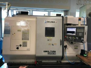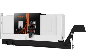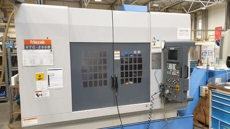
Technical Buyer’s Handbook: Assessing Pre-Owned , Used , Secondhand, Surplus CNC Machines Before Purchase Mazak VTC 200 B made in Japan
Here is a Technical Buyer’s Handbook / Due-Diligence Checklist you can use when evaluating a pre-owned / used / surplus Mazak VTC-200B vertical machining center (Japan origin). Use this as a structured guide; adapt tolerances and weighting to your part requirements, volume, and risk tolerance.
I’ll start with a rough spec summary (from used listings) to give you benchmarks, then a detailed inspection & testing checklist, risk assessment, negotiation safeguards, and post-installation commissioning notes.
I. Reference / Benchmark Specifications (Mazak VTC-200B)
Before visiting the machine, collect or confirm the actual spec sheet for that serial number. Below are typical specs from used listings to guide your expectations:
| Parameter | Nominal / Typical Value |
|---|---|
| Travels (X × Y × Z) | 44.09″ × 20.08″ × 20.08″ (≈ 1,117.6 × 508 × 508 mm) |
| Table size | ~ 57.48″ × 20.08″ (≈ 1,460 × 510 mm) |
| Max table load / workpiece weight | ~ 1,760 lbs ≈ 800 kg |
| Spindle speed | Up to 10,000 rpm, sometimes claimed up to 12,000 rpm in some ads |
| Spindle power / motor | ~ 20 HP (≈ 14.9 kW) for many used units |
| Tool changer capacity | 24 pockets, side-mount style in many listings |
| Weight / footprint | ~ 6,100 kg (some listings) |
| Control system | Mazatrol 640M / Mazatrol Fusion 640 variants in many used machines |
| Spindle taper | CAT/CT 40 (or No. 40) in many cases |
Use these as “target” references. A used machine will deviate somewhat, but large discrepancies (e.g. much lower spindle rpm, significant loss of travel, heavy wear) must be explained or become negotiation points.
II. Pre-Inspection / Remote Phase (Before On-Site Visit)
Before going, gather as much documentation, photos, and preliminary data as possible:
- Original Mazak manuals (mechanical, electrical, hydraulic, lubrication)
- Wiring diagrams, CNC parameter backups, I/O lists
- Maintenance / service logs (spindle rebuilds, axis overhauls, major repairs)
- Calibration / alignment certificates, inspection reports
- Records or evidence of modifications / upgrades (e.g. spindle upgrades, added probing, retrofit controls)
- List of tooling, fixtures, accessories included
- High-resolution photos / videos of: machine exterior, interior cabinets, spindle & tooling area, axis guides, tool changer, wiring, drives
- Ask the seller:
• Year, total run hours, spindle hours
• Reason for sale
• Any known defects or maintenance issues
• Spares included
• Is the machine currently operational?
• Control software / version state
• Whether the machine ever had catastrophic failure (collision, coolant ingress, etc.)
Also plan to bring or prepare: dial gauges, micrometers, test bars, straight edges, laser alignment tools (if available), vibration meter, thermography camera, borescope, etc.
Plan logistics: weight, lifting / rigging, access, floor strength, utilities (power, coolant, air), foundation.
III. Visual & Structural Inspection (Cold, Power-Off)
Walk around and inspect everything carefully before powering up. Many defects or wear signs are visible at this stage.
1. Machine Frame, Base & Structure
- Inspect casting, bed, column, base for cracks, welding repairs, distortions, sagging
- Check anchor and base mounting surfaces; any signs of re-machining or leveling adjustments
- Check guards, covers, way covers, bellows, scrapers for damage, missing parts
- Check coolant trays, chip conveyors, sumps for corrosion, leaks, residue build-up
- Assess cleanliness: excessive chips or coolant residue may signal neglected maintenance
2. Linear Axes, Guideways & Carriages
- Inspect linear guide rails / ways / slides for wear, scoring, spalling, foreign particles
- Check for pitting, rust, scratches along sliding surfaces
- Inspect ball screws or drive mechanisms for wear, damage, and lubrication condition
- Check backlash / looseness in nuts or anti-backlash mechanisms
- If possible, manually move axes (light push) to feel binding, stiction, uneven resistance
- Inspect lubrication / grease lines, reservoirs, condition of lubricant (contamination)
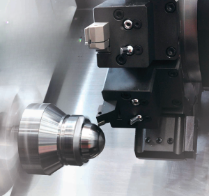
3. Spindle, Nose, Tool Interface & Cooling
- Examine spindle nose, taper, threads, seating surfaces for damage, corrosion, wear
- Inspect bearings seals for leakage or discoloration (overheated)
- Check coolant / lubrication lines to the spindle; inspect any rotary union, hoses, seals
- If possible, insert test bar (non-powered) and check for static run-out
- Inspect spindle motor, couplings, alignment to the drive
4. Tool Changer, Tool Holders & Magazine
- Inspect changer arms, grippers, slides for wear, play, misalignment
- Check sensors, switches, pneumatic/hydraulic actuation mechanisms
- Examine tool pockets, magazine rails, indexing gear or carousel surfaces
- Check cable routing to tool changer motors / sensors for wear
5. Electrical Cabinets, Wiring & Drives
- Open cabinets (if allowed) and inspect internal wiring, connectors, terminal blocks, wiring bundling
- Look for evidence of overheating: discolored insulation, melted zones, burned connectors
- Inspect power modules, servo drives, control boards, I/O modules
- Check for moisture, dust, corrosion inside enclosures
- Inspect ventilation fans, dust filters, cooling paths
- Check cable carriers / drag chains on axes for frayed cables, wear
6. Safety / Guards / Interlocks
- Confirm emergency stop (E-stop) buttons exist and appear mechanically sound
- Inspect safety interlock switches, guard doors, enclosure panels
- Verify no safety circuits are bypassed (e.g. taped sensors, open covers)
- Check limit switches, travel stops, home switches for integrity
IV. Power-Up & Functional / Dynamic Testing
Once structural inspection is acceptable and safety is assured, proceed with dynamic tests (with care). This is where you test how the machine actually performs under motion, load, and control.
1. Initial Power-On & Diagnostics
- Power up control / CNC; observe boot, alarm logs, errors
- Verify parameter memory, variable backup files
- Check I/O signals: limit / home switches, safety interlocks, sensor statuses
- Jog axes at low speed, check directions, smoothness, no binding
2. Homing / Reference Cycle
- Execute homing / referencing on all axes (X, Y, Z)
- Repeat multiple times; check consistency / repeatability of home positions
- Trigger limit switches to confirm they function and do not overshoot
3. Axis Motion & Travel Tests
- Move axes across full safe travel (within limits) at moderate speeds; observe any jerk, stall, vibration
- Command known moves (e.g. 100 mm, 200 mm) and measure actual movement with a dial gauge or reference device
- Reverse direction and measure backlash or dead zone
- If available, use a ball-bar or laser interferometer to test straightness, linearity, squareness across axes
4. Spindle Running Test
- Start spindle at low RPM; observe behavior, noise, vibration
- Ramp to higher RPM (within safe limits); monitor for vibration, instability
- Measure dynamic run-out if possible (test bar while spinning)
- Monitor spindle motor current, torque draw, heat dissipation
- Check coolant / lubrication flow to spindle under load
5. Tool Change / Tool Handling Test
- Perform multiple tool change cycles; observe timing, sensor response, gripper movement
- Cycle through many tool changes to test reliability
- Load tooling, run movements, check that no collisions or misplacements happen
6. Test Cut / Machining Simulation (if allowed)
- Run a light-cut test (e.g. on mild steel or aluminum) to simulate actual machining
- Measure final part geometry vs programmed, check surface finish
- Run for extended period (e.g. 30–60 minutes) to assess stability, drift, temperature effects
- Monitor current draw, vibration, thermal growth
7. Safety / Fault Behavior Tests
- Trigger E-stop while axes are moving or spindle is spinning; verify immediate safe stop
- Actuate limit switches to see if the machine halts or backs off properly
- Simulate sensor faults (if safe) to test control error handling
- Check guard / door interlock behavior during operation
8. Endurance / Stability / Drift Test
- Run continuous motion / idle cycles to allow thermal stabilization
- After warm-up, re-check positioning, backlash, repeatability to detect drift
- Monitor temperatures of drives, motors, cabinet
- Use vibration sensor or thermography to find emerging anomalies
V. Precision, Accuracy & Calibration Testing
Once the machine is stable, perform precision and calibration measurements to see whether it meets tolerances.
- Perform repeatability test: move to same coordinate repeatedly, measure deviation
- Execute a grid of points motion (X vs Y sweeps) and measure positional errors across the workspace
- Compare measured values to Mazak spec tolerances or your acceptance tolerances
- Test squareness, flatness, parallelism by measuring relative movement in orthogonal directions
- If available, use laser interferometer / alignment instruments for higher accuracy
- Test under load / offset conditions (heavy part or offset center) to see deflection or dynamic error
VI. Documentation & History Review
After inspection, carefully scrutinize the machine’s background and records.
- Maintenance / repair log: all major overhauls, spindle rebuilds, axis repairs
- Calibration / alignment records
- Retrofit / upgrade history (spindle, control, axis modules)
- CNC / control software version history, backups
- Spare parts inventory included
- Tooling, fixtures, accessories transferred with machine
VII. Risk Assessment, Life-Remaining Estimation & Cost Projection
Based on the tests and inspection, build a risk & cost forecast.
- Wear-prone subsystems: spindle bearings, lead screws, guide rails, tool changer
- Spare parts availability / cost: Mazak parts cost and regional support
- Calibration / realignment cost: after transport, installation, you’ll need precise alignment
- Transport / installation risk: damage in transit, reassembly, foundation, leveling
- Downtime & commissioning: time to make the machine production-ready
- Control / electronic obsolescence: age of drives, modules, CNC electronics
- Fallback / salvage value: structural parts, usable subsystems
You can assign weights to subsystems (spindle, axes, control, mechanism) to derive a health score and adjust your maximum acceptable price accordingly.
VIII. Contractual Safeguards & Negotiation Terms
Your inspection empowers negotiation points and contract clauses:
- Acceptance test clause: your offer is contingent on passing the performance tests once machine is installed
- Price adjustment clause: if key metrics deviate, you deduct repair / correction costs
- Warranty / latent defect guarantee: e.g. 3–6 months for hidden defects in spindle or control
- Spare parts package: seller to provide critical spare parts (bearings, seals, tools)
- Documentation handover: manuals, wiring, backup files, drawings
- Transport & insurance terms: who bears risk of damage in transit
- Installation / commissioning support: seller helps or provides technical support for first setup
IX. Post-Purchase / Installation & Commissioning Checklist
Once delivered and reinstalled, follow a thorough commissioning regimen:
- Foundation preparation, leveling, anchoring
- Clean machine, flush coolant / lubrication systems, replace filters
- Re‐install covers, guards, safety systems
- Power up and re-run acceptance test suite
- Perform alignment, geometry calibration, error compensation
- Run test parts in actual materials and verify tolerances
- Capture baseline data (repeatability, drift, backlash)
- Train operators & maintenance staff on machine quirks
- Establish preventive maintenance schedule
- Monitor performance (drift, errors, vibrations) in early production