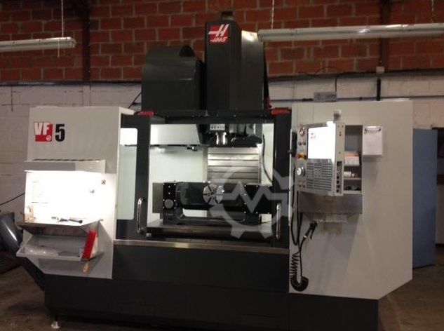
Technical Buyer’s Handbook: Assessing Pre-Owned , Used , Secondhand, Surplus CNC Machines Before Purchase HAAS VF 5 made in USA
Here is a Technical Buyer’s / Due-Diligence Handbook / Checklist you can use when assessing a pre-owned / used / surplus Haas VF-5 vertical machining center (made in USA). You should adapt tolerances, priorities, and weightings to your shop’s requirements (part size, precision, throughput).
I. Reference / Benchmark Specs
Before inspection, assemble the nominal specifications for the specific variant. This gives you targets to compare against. Some typical specs from used-machine listings:
| Parameter | Typical / Known Value |
|---|---|
| Travel (X × Y × Z) | ~ 50″ × 26″ × 25″ (1,270 × 660 × 635 mm) |
| Table size | ~ 54″ × 24″ (1,372 × 610 mm) |
| Max table load (even distribution) | ~ 4,000 lbs ≈ 1,814 kg |
| Spindle speed | Up to ~ 8,100 rpm (many units) |
| Spindle motor / power | 30 HP is often cited in used ads |
| Tool changer | 20 or 30 tools in listings |
| Rapid traverse | ~ 710 IPM (≈ 18 m/min) in axes |
These are reference benchmarks, not binding limits. A used machine naturally will deviate from them; your job is to assess whether deviations are acceptable or repairable.
II. Pre-Inspection / Remote Preparation
Before you visit:
- Obtain documentation
- Mechanical, electrical, hydraulic / coolant manuals
- Wiring diagrams, control parameter backups, axis tuning files
- Service and maintenance logs: what has been replaced, repairs, downtime events
- Calibration / alignment reports
- Any modifications or retrofits (e.g. spindle upgrades, 4th/5th axis prep)
- Parts list / spare parts listing - Request photos & videos
- Exterior, machine frame, guards
- Inside cabinets: drives, wires, terminal blocks
- Spindle, tool changer, tool holders
- Guideways, ball screws, axis carriages
- Animation or videos of axis jogs, tool change (if machine is live) - Ask key questions
- Year of build, cumulative run hours
- Reason for sale
- Is it currently powered / functioning?
- Known defects or past collisions
- What major subsystems were replaced (spindle bearings, ball screws, etc.)
- Are spare parts / tooling included? - Bring / prepare inspection tools
Dial gauges, micrometers, test bars, straight edges, borescopes, alignment lasers (if possible), vibration meter, thermography camera - Logistics assessment
Machine weight, rigging / lifting plan, floor loading, power / coolant / air infrastructure, foundation requirements
III. Visual & Structural Inspection (Power-Off)
Walk around and inspect thoroughly all structure and mechanical subsystems before powering up.
1. Frame & Base
- Examine casting, column, base for cracks, welds, distortions
- Ensure base pads, shims, mounting surfaces are intact and not excessively worn
- Look for corrosion, pitting especially in coolant / chip zones
- Check all guarding, covers, way covers, bellows for damage or missing parts
2. Linear Axes & Guides
- Examine guide rails, linear bearings, carriage surfaces for scoring, wear, pitting
- Inspect ball screws / nuts, support bearings, backlash / play
- Check anti-backlash / preload mechanisms (if present)
- If possible, manually slide axes to feel binding, inconsistent friction
- Inspect lubrication lines, fittings, cleanliness of oil / grease
3. Spindle & Nose
- Inspect spindle nose, taper, clamping surfaces, threads for wear, rounding, damage
- Check bearing seals for leakage, discoloration (signs of overheating)
- Inspect cooling / lubrication lines to spindle, seals, union connections
- If possible, mount test bar and measure static run-out
4. Tool Changer / Tool Handling
- Inspect changer arms, grippers, slides for wear, looseness
- Check sensor switches, actuation (pneumatic, hydraulic, servo) hardware
- Inspect magazine, pockets, indexing mechanism
5. Electrical Cabinets & Wiring
- Open control / drive cabinets; inspect wires, connectors, terminal blocks for discoloration, burnout, looseness
- Inspect drives, power modules, control boards for signs of overheating or damage
- Check ventilation, filters, fans, dust ingress
- Review cable routing, strain relief, cable carriers on axes
6. Safety / Interlocks
- Confirm presence and mechanical integrity of emergency stop(s)
- Inspect door interlocks, limit switches, home switches
- Verify that safety circuits are not bypassed
- Check guards over moving or cutting zones
IV. Power-Up & Functional / Dynamic Testing
With safety precautions, power up and execute dynamic tests.
1. Control & Diagnostics
- Power-on CNC / control; watch boot, error logs
- Verify parameter memory, loaded configuration
- Check I/O status: limit switches, home, safety inputs
2. Axis Jog & Homing
- Jog axes slowly: observe direction, smoothness, stiction
- Execute homing / reference cycles; repeat to check consistency
- Test limit / soft limit behavior
3. Axis Motion & Accuracy
- Move across full axis travels at moderate speeds; observe irregular behavior, binding, vibration
- Command known distances (e.g. 100 mm) and measure actual with dial indicator or gauge
- Reverse direction to detect backlash / dead zone
- If possible, run a ball-bar or geometric test for straightness, linearity
4. Spindle Run Test
- Start spindle at low RPM, gradually ramp up, observe noise, vibration
- Measure dynamic run-out under rotation
- Monitor motor current, temperature behavior
- Confirm spindle cooling / lubrication under motion
5. Tool Change & Magazine Test
- Execute multiple tool changes; monitor timing, sensor responses, consistency
- Cycle many times to test reliability and detect failures
- Load various tools and check pocket alignment
6. Test Cut / Machining Simulation (if permissible)
- Run a light cut on soft material
- Measure part geometry vs program, check surface finish
- Run for extended period to detect drift, thermal effects
- Monitor vibrations, current draw
7. Safety / Fault Response
- Trigger E-stop during motion or spindle — confirm safe stop
- Cause limit switch triggers — confirm safe behavior
- Simulate sensor failure (if possible) to observe error handling
- Test guard / door interlock behavior
8. Endurance / Stability Test
- Run motion or idle cycles to allow thermal stabilization
- After warm-up, retest key positions, backlash, repeatability
- Monitor temperatures of motors, drives, control cabinet
- Use vibration analysis or thermography to spot anomalies
V. Precision, Calibration & Accuracy Testing
Once the machine is thermally stable:
- Perform repeatability tests: move to a point, retract, return, measure deviation
- Execute grid or pattern motion (X–Y sweep) and measure positional deviation across the workspace
- Check squareness, flatness, orthogonality by comparing cross-axis motion errors
- If available, use laser interferometer or calibration tools for high-accuracy error mapping
- Test under load / offset part positions to reveal deflection
- Compare results to accepted tolerances or Haas spec (if available)
VI. Documentation & History Review
Review the machine’s background:
- Maintenance / repair logs, major overhauls
- Replaced components (bearings, balls screws, spindle rebuilds)
- Calibration / alignment certificates
- Modifications / upgrades (spindle, controls, additional axes)
- Control / software version history, backups
- Spare parts, tooling, accessories included
VII. Risk Assessment, Life-Remaining & Cost Forecast
Based on inspection results:
- Identify wear-critical subsystems (spindle bearings, ball screws, guides, changer)
- Estimate remaining life / risk exposure
- Check parts availability and lead times for Haas components
- Budget calibration / re-alignment cost post-move
- Estimate transport / installation risk (damage, alignment)
- Project downtime / commissioning time
- Consider control / electronics obsolescence
- Estimate fallback / salvage value
You may build a weighted score sheet across subsystems to guide your maximum acceptable price or repair allowance.
VIII. Contractual Safeguards & Negotiation Terms
Use your findings to shape contract protections:
- Acceptance test / performance clause: your purchase contingent on passing your tests post-installation
- Price adjustment clause: for deviations beyond acceptable tolerances
- Warranty / latent defect coverage: e.g. 3–6 months on critical systems
- Spare parts package: require key wear parts (bearings, seals, tools) included
- Documentation delivery: all manuals, wiring, parameter backups, drawings
- Transport & insurance responsibility: define who bears risk during shipping
- Installation / commissioning support: seller or their agent assists initial setup
IX. Post-Purchase / Installation & Commissioning Checklist
Once the machine is delivered and set up:
- Foundation, leveling, anchor, vibration isolation
- Clean and flush coolant / lubrication systems, replace filters
- Reinstall covers, guards, safety devices
- Power-up and rerun acceptance / functional test suite
- Perform alignment, error compensation, calibration
- Run test parts in real production materials and validate tolerances
- Capture baseline performance metrics (backlash, drift, repeatability)
- Train operators & maintenance staff
- Establish a preventive maintenance schedule
- Monitor performance (drift, alarms, deviations) closely in early production