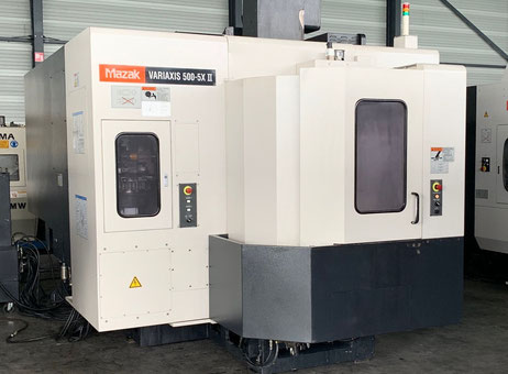
Technical Buyer’s Handbook: Assessing Pre-Owned , Used , Secondhand, Surplus CNC Machines Before Purchase Mazak Variaxis 500-5x II made in Japan
Here is a Technical Buyer’s Handbook / Due-Diligence Checklist you can use (and adapt) when evaluating a pre-owned / used / surplus Mazak Variaxis 500-5X II (5-axis vertical machining center, made in Japan). Use this as a structured and prioritized guide; you may weight subsystems differently depending on your application, tolerances, and risk tolerance.
0. Reference / Benchmark Specifications (Mazak Variaxis 500-5X II)
Before going to the site, collect or confirm the nominal specifications (for the exact serial / configuration) so you know what “healthy” looks like. Below are typical published specs for the Variaxis 500-5X II variant:
From dealer / spec sources:
- X / Y / Z travels: 510 mm × 510 mm × 460 mm
- Table size: 500 mm × 400 mm
- Maximum table load / workpiece weight: ~ 300 kg
- Spindle power: 22 kW (approx)
- Spindle speed: 12,000 rpm
- Tool magazine / ATC slots: around 30 tools in many listings
- Tilting table / rotary axes ranges: A-axis typically –120° to +30°, C-axis full 360° indexing
- Rapid traverse: e.g. 1969 IPM for many machines
These published numbers set your “ideal / target” expectations. When inspecting a candidate machine, you’ll compare measured performance to these.
I. Pre-Inspection / Remote Phase (Before Visiting Site)
Before you go, gather as much documentation, photos, and data as possible so you arrive well informed.
- Documentation Request
- Original Mazak manuals (mechanical, electrical, hydraulics / coolant, spindle, rotary table)
- Wiring diagrams, I/O maps, control / CNC parameter backups, axis tuning files
- Maintenance / service logs: spindle rebuilds, rotary axis servicing, guide rail replacement, drive repairs
- Calibration / alignment / error compensation certificates
- Records of any upgrades or retrofits (higher power spindle, tool changer upgrades, probing or 4th/5th axis kits)
- Spare parts list / BOM - Photos & Videos
Ask the seller for high-resolution images and, if possible, video walkthroughs (or live demo) of:
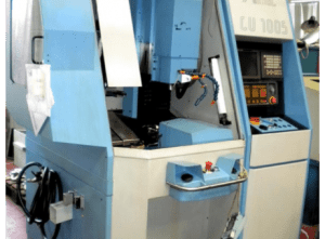
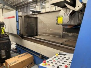
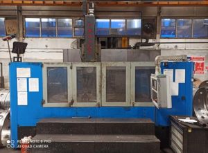
• Machine exterior: frame, guards, covers
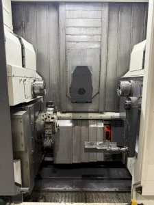
• Rotary / tilting table, axes, bearings
• Spindle head, nose, tool change area
• Guideways, ball screws, axis carriages
• Electrical cabinets: drive racks, wiring, terminal blocks
• Control panel, buttons, interface
• Motion videos (axis jogging, table rotation) - Key Clarifying Questions
- Year of manufacture, serial number
- Total hours / duty cycle (spindle hours, table rotation hours)
- Reason for sale / decommission
- Whether it is currently in working order or deactivated
- Known issues / history of collisions, repairs
- Which major components have been replaced and when
- Whether tooling, fixtures, probes, spares are included
- CNC control version / software license state - Bring or Plan for Inspection Tools
- Dial indicators, micrometers, test bars, straight edges
- Optical alignment tools or laser interferometer (if available)
- Vibration sensor / accelerometer
- Thermography / IR camera
- Torque wrenches, feeler gauges, calibration blocks
- Tools for opening panels / covers - Logistical / Facility Planning
- Machine weight, footprint, access / crane / rigging plan
- Power, cooling, exhaust, air, hydraulic connections required
- Foundation / floor flatness, load capacity
- Space around machine for service and motion
II. Visual & Structural Inspection (Machine Cold / Power-Off)
Once on site, before or alongside powering the machine, do a detailed structural and component inspection.
1. Frame, Base, Support Structure
- Inspect castings, columns, base for cracks, weld repairs, signs of fatigue or distortion
- Check foundation interface: anchor points, shim plates, any history of foundation rework
- Look for corrosion, rust, pitting especially in coolant zones, splash areas
- Inspect covers, guarding, glazing windows (if enclosed), seals, way covers, bellows for damage or wear
- Check that machine is square, level, and not twisted (visual checks using straight edges)
2. Linear Axes, Guideways & Ball Screws
- Examine guide rails, linear bearings / slides for wear marks, spalling, contamination
- Inspect ball screws (or drive mechanisms) for wear, pitting, backlash
- Check support bearings at ends, coupling conditions
- Manually push axes (if safe) to sense binding, uneven friction
- Inspect lubrication / grease / oil systems: lines, fittings, blockages, cleanliness of lubricant
3. Rotary / Tilting Table (A / C Axes)
- Inspect rotary table bearings, tilting mechanism, table mounting surface
- Check for play, backlash in rotary or tilt axes
- Inspect adjustment / preload mechanisms, seals, lubrication for those axes
- Check cable routing, cable carriers, slip rings or rotary joints
- Examine the plating or reference surfaces on the table for wear or damage
4. Spindle & Tool Interface
- Inspect spindle nose, taper, threads, clamping surfaces for signs of wear, unevenness, damage
- Check seals, cooling or lubrication lines feeding the spindle
- If possible, mount a test bar (non-rotating) to check static run-out before motor drive
- Inspect motor coupling (if applicable) and alignment to the spindle
- Check for overheating / discoloration signs, lubricant leakage
5. Tool Changer / Magazine / Tool Holding System
- Inspect tool changer arm(s), grippers, slides for wear, looseness, misalignment
- Check magazine pockets, indexing mechanism, detection sensors
- Inspect pneumatic / hydraulic actuation circuits, valves, sensors
- Check wiring, connectors to tool changer motors / sensors
6. Electrical Cabinet, Wiring & Drive Hardware
- Open machine / control cabinets (if permitted) and inspect internal wiring, connectors, terminal blocks
- Look for discoloration, overheating marks, burning, melted insulation
- Check drive modules, power modules, control boards for signs of failure or stress
- Inspect cooling fans, filters, ventilation paths, dust accumulation
- Examine cable carriers / drag chains from axes for frayed or fatigued cables
7. Safety, Interlocks & Guards
- Confirm emergency stop (E-stop) buttons exist and are mechanically solid
- Inspect door / guard interlocks, limit switches, home switches for function and condition
- Verify that safety wiring is intact and not bypassed
- Check that guards cover all moving or hazardous zones
III. Power-Up & Dynamic / Functional Testing
Once the static checks are acceptable and safety is assured, power up the machine and perform dynamic tests under controlled, cautious conditions.
1. Control & Diagnostics
- Power on control / CNC; monitor boot sequence, error logs, alarm messages
- Verify that CNC parameters, axis tuning, offsets, compensation tables load successfully
- Check I/O: ensure limit switches, home sensors, interlock input statuses are correct
- Jog axes slowly; observe direction, smoothness, no odd noise or binding
2. Homing / Reference Cycles
- Execute homing / referencing of all linear and rotary / tilting axes
- Repeat homing multiple times to assess position repeatability
- Test limit / soft limit functions, ensure axes do not crash or overshoot
3. Axis Motion Tests & Accuracy
- Traverse axes over their full usable travel ranges at moderate speeds, watching for smoothness, jerk, vibration
- Command known moves (e.g. 100 mm, 200 mm) and measure with dial gauge or reference instrument to verify linear accuracy
- Reverse direction and measure backlash or dead zone
- If available, perform a ball-bar or geometric test to evaluate straightness, squareness, linearity
4. Spindle / Rotation Test
- Start spindle at low rpm and gradually ramp up, observing for vibration, misbehavior
- Measure dynamic run-out (test bar while spinning)
- Monitor spindle motor current, torque, temperature stability
- Confirm spindle cooling / lubrication behavior under motion
5. Tool Change & Magazine Tests
- Run multiple tool change cycles; monitor timing, smoothness, sensor responses
- Cycle many times to detect intermittent issues or failure
- Attempt tool change under variety of tool lengths / weights (if safe)
6. Part Cutting / Machining Simulation (if safe)
- If possible, perform a light cut (soft material) using 5-axis motions to test real behavior
- Measure part accuracy vs programmed dimensions, check surface finish
- Run multi-minute sequences to allow for thermal effects, drift
- Monitor for chatter, acceleration lag, axis coupling anomalies
7. Safety & Fault Handling Tests
- Trigger E-stop during motion or spinning; machine must stop safely
- Cause limit switch triggers (if possible) to check safe motion stop or retraction
- Simulate sensor failures or communication faults to observe error handling
- Verify guard / door interlock behavior during motion
8. Extended / Endurance Testing & Stability
- Run repeated motion cycles or idle for extended time (30–60 min) to let the machine thermalize
- After warm-up, re-check key axes, backlash, repeatability to detect shift
- Monitor motor, drive, control cabinet temperatures
- Use vibration sensors or thermography to identify developing issues
IV. Accuracy, Calibration & Precision Validation
Once the machine is thermally stable, perform precision tests to see whether it meets your required tolerances.
- Repeatability test: move to a coordinate, retract, return; measure deviation
- Grid / mapping test: execute an array of positions (X–Y plane, with tilts) and measure deviations
- Volumetric accuracy: in 5-axis you want to check combined linear + rotary error (if you have access to a volumetric calibration system)
- Rotary / tilting axis precision: command angular moves and measure deviation, backlash, tilt coupling
- Cut-to-cut consistency: produce repeated parts, measure variation
- Use high-precision instruments (laser interferometer, calibration spheres) if available
- Compare measured deviations against Mazak’s published tolerances or your acceptance thresholds
V. Documentation, Service History & Records Review
After testing, carefully review the machine’s background and support documentation.
- Maintenance / service / repair logs: bearing replacements, axis overhauls
- Calibration / alignment / compensation records
- History of retrofits or modifications
- CNC / software version / upgrade records, backup files
- Spare parts inventory included (optics, probes, tooling, bearings)
- Tooling, fixtures, probes, adapters included
VI. Risk Assessment, Life-Remaining Estimate & Cost Forecasting
Based on what you see, you should build a risk profile and cost forecast.
- Critical wear subsystems: rotary bearings, tilting bearings, linear guides, ball screws, tool changers, drive systems
- Spare parts / support risk: availability of Mazak 5-axis parts, lead times, cost
- Calibration / realignment cost: 5-axis machines require careful calibration after relocation
- Transport / installation risk: careful handling of the tilting table, alignment shift, cabling
- Commissioning downtime: time until production-ready
- Control / electronics obsolescence: age of CNC, drive modules, interface boards
- Fallback / salvage: what parts remain useful if machine fails
You may create a weighted scoring model across subsystems (structure, axes, rotary, spindle, control) to quantitatively assess condition and guide your offer.
VII. Contractual Safeguards & Negotiation Provisions
Use your inspection leverage to negotiate protection clauses:
- Acceptance / performance clause: the sale is contingent on passing on-site and post-installation tests (accuracy, motion)
- Price adjustment clause: if performance is worse than agreed thresholds, deduct repair cost
- Warranty / latent defect clause: e.g., 3–6 months coverage on hidden faults
- Spare parts package: demand inclusion of key wear parts (bearings, seals, tool changer parts)
- Documentation delivery: full manuals, wiring diagrams, software/parameter backups, alignment data
- Transport / insurance clause: define liability for damage during transit
- Commissioning support clause: seller or authorized technician assists or supervises initial installation
VIII. Post-Purchase / Installation & Commissioning Checklist
Once delivered and installed in your facility, do the following before full production:
- Foundation, leveling, anchoring, vibration isolation
- Cleaning, flushing coolant / lubrication systems, replacing filters / fluids
- Re-install guards, covers, safety interlocks
- Power-up and re-run acceptance / functional tests
- Perform alignment, calibration, error compensation (volumetric calibration for 5-axis)
- Run test parts in your real materials to validate performance
- Record baseline measurement data (repeatability, drift, backlash)
- Train operators & maintenance staff on quirks, procedures
- Establish preventive maintenance schedule (especially for 5-axis axes)
- Monitor performance (drift, errors, alarms) in the early weeks