Technical Buyer’s Handbook: Assessing Pre-Owned , Used , Secondhand, Surplus CNC Machines Before Purchase Moore G18 CNC Jig Grinder Machine made in USA
Below is a Technical Buyer’s Handbook / Due-Diligence Checklist for evaluating a pre-owned / used / surplus Moore G18 (or similar) CNC / jig grinder made in the USA. Because jig grinders are precision machines with tight tolerances, the inspection must be rigorous. Use this as a guide and adapt to your tolerance needs, tooling, and budget.
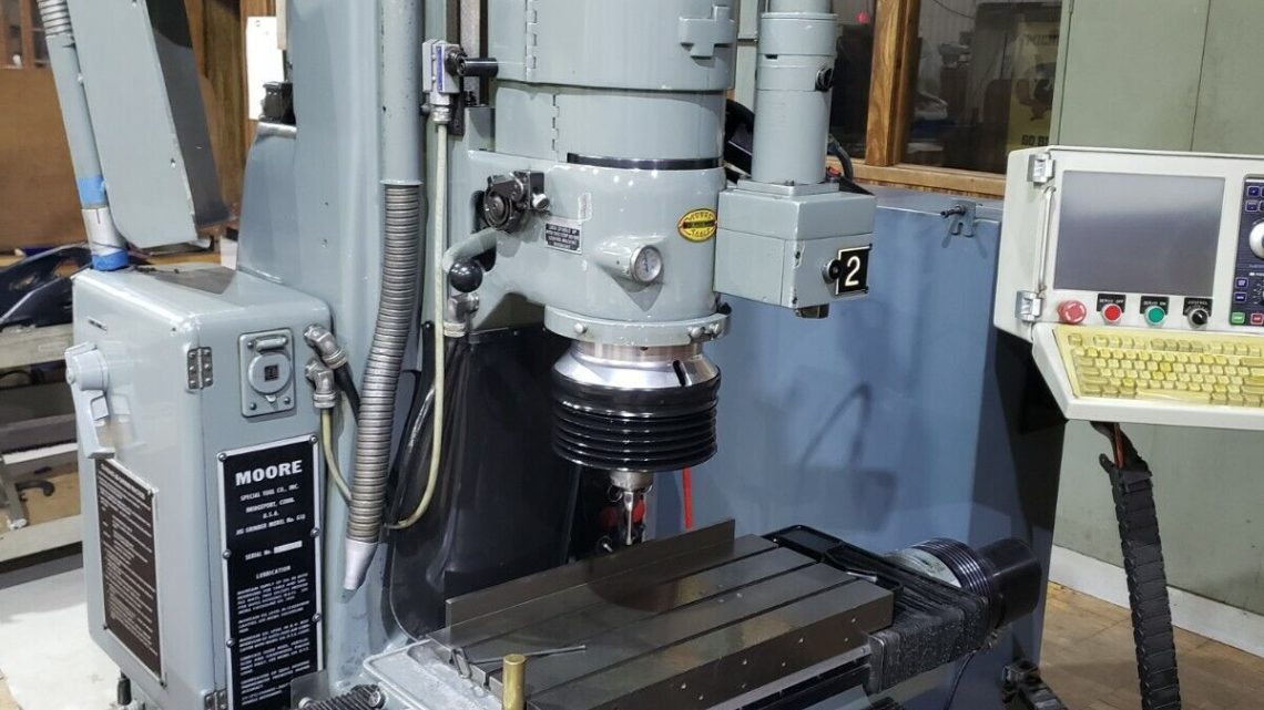
I. Reference / Benchmark Data (Moore G18 Typical Specs)
Before inspecting, gather or confirm the nominal / factory specs for the machine you’re considering. Below are typical data points for Moore G18 / No. 3 jig grinders from used-machine listings:
| Parameter | Typical / Published Value |
|---|---|
| Table size | 11″ × 24″ (width × length) |
| Table travel (X / Y) | 18″ longitudinal × 11″ cross |
| Spindle housing vertical travel | ~ 12-5/8″ |
| Spindle quill / vertical travel | ~ 3-5/8″ (quill / spindle head internal movement) |
| Table-top to wheel collet distance | 2″ to 18″ range |
| Spindle speeds (main) | 40 to 250 rpm (infinitely variable) |
| Grinding wheel (wheel spindle) speed | 9,000 to 40,000 rpm (or more in some configurations) |
| Angular adjustment of spindle | ± 0.15° (adjustment in small angle) |
| Approximate weight | ~ 4,000 lbs (≈ 1,800-2,000 kg) |
These are target values to compare your candidate against. Deviations might indicate wear, misalignment, or modifications.
II. Pre-Inspection / Remote Phase (Before Arrival)
Before visiting, collect as much background and documentation as possible to reduce surprises.
- Request documentation
- Moore G18 manuals (mechanical, electrical, lubrication, spindle / grinding head)
- Wiring diagrams, control schematics
- Maintenance records: spindle rebuilds, bearing changes, overhauls
- Calibration / alignment / inspection certificates (geometry, table, spindle)
- Modification / upgrade history (e.g. higher rpm head, CNC retrofit)
- Spare parts list / parts availability - Request photos & videos
Ask images / video showing: frame, table, spindle head, column, guide rails, wiring cabinets, spindle head internals (if accessible), motion (if still running) - Key questions to ask
- Year, serial number, total hours / duty cycle
- Whether the machine is operational at present
- Known problems / repairs / collision history
- Spare parts included
- What subsystems have been replaced or overhauled - Prepare inspection / measurement tools
Dial indicators, test bars, straight edges, precision squares, alignment tools, optical devices, temperature / vibration sensors - Logistics / site planning
Machine footprint, crane / hoist access, foundation / floor flatness, power / utilities, cooling / air supply
III. Visual & Structural Inspection (Power-Off / Cold)
Before powering up, inspect structural integrity and visible mechanical subsystems thoroughly.
1. Frame, Base & Column
- Inspect the machine frame, column, base for cracks, weld repairs, distortion
- Check for signs of rework or leveling shims being altered
- Inspect surfaces for corrosion, pits, rust, especially in coolant / chip zones
- Check mounting points, base bed for flatness and alignment conditions
2. Table & Guideways, Carriages
- Inspect table surfaces: wear, scratches, flatness, surface finish
- Check guideways / bed ways for wear, scoring, pitting
- Inspect carriages / slides for looseness, slop, binding
- Check backlash or play between table and carriage
- Look at lead screws / drive mechanisms (if present) for wear, backlash
3. Spindle Head / Grinding Spindle / Quill
- Inspect spindle nose, collet interfaces, mounting surfaces for wear, damage
- Check quill / spindle head vertical motion (if accessible) for binding or play
- Inspect seals, lubrication lines, cooling plumbing to spindle or grinding head
- Inspect the grinding head rotor, spindle assembly, any collets or adaptors
- Look for discoloration or signs of overheating
4. Grinding Wheel Spindle / Head / Optics
- Inspect the wheel spindle, balancing adaptation, collets, wheel mounts
- Inspect guard covers, enclosures for wheel, chucks, protective guarding
- Check for dust / buildup, damage around the wheel area
- Confirm wheel guard / cover interlocks are intact
5. Electrical / Control Cabinets & Wiring
- Open control cabinets (if permitted) and inspect wiring terminations, connectors, panels
- Look for discoloration, burnt wires, signs of overheating
- Check drive modules, control boards, I/O modules, power supplies
- Inspect cable routing, strain reliefs, shielding
- Examine wiring in moving parts (head, carriage) for fatigue or abrasion
6. Safety / Guards / Interlocks
- Check emergency stops (E-stop) mechanical integrity
- Inspect guard doors, covers, interlock switches
- Ensure safety circuits not bypassed
- Check limit switches, home switches, motion interlocks
IV. Power-Up & Functional / Dynamic Testing
Once basic inspection is acceptable and safety is assured, proceed to dynamic tests carefully.
1. Control & Diagnostic Verification
- Power-on control (CNC or DRO system) and check boot sequence, error logs
- Confirm parameter memory / configuration integrity
- Verify I/O input status (limit, home, safety)
- Jog axes (X, Y, vertical / spindle head) slowly, observe direction and smoothness
2. Homing / Reference Moves
- Execute homing / reference (if available) for axes
- Repeat homing multiple times, check for consistency / repeatability
- Trigger limit or safe stops to test proper response
3. Axis Motion & Accuracy Tests
- Move table across full available travel at moderate speeds, watching for binding, jerk, odd noises
- Command known increments (e.g. 10 mm, 50 mm) and measure actual displacement via dial gauge / test device
- Reverse direction to detect backlash or dead zone
- For vertical travel (spindle housing movement) check smoothness and consistency
4. Spindle & Grinding Head Tests
- Spin the spindle / grinding head (if safe) at low to mid rpm to test for vibration / noise
- Monitor motor current, stability, heating
- If possible, mount a test wheel and check dynamic balance or run-out
- Check cooling / lubrication flow during spindle motion
5. Grinding Simulation / Test Cut (if safe)
- If allowed, try a light grind on a practice part or test plate
- Measure resulting geometry, tolerance, surface finish
- Let machine run for some time to assess drift, thermal effects
- Monitor currents, vibrations, stability
6. Safety / Fault Tests
- Press E-stop during motion / spindle: ensure immediate, safe shutdown
- Trigger limit switches / home switches: axes must stop or retract safely
- Check guard / interlock behavior while motion is active
7. Extended Stability / Drift / Endurance Test
- Run cycles or idle motion for 30–60 min to allow thermal stabilization
- After warm-up, re-check key axes, backlash, repeat motion to detect drift
- Monitor temperatures (motors, cabinet, spindle)
- Use vibration / thermal tools to detect localized heating or anomalies
V. Precision, Calibration & Accuracy Validation
Once warm and stable, perform precision measurements to assess whether the machine meets tolerance requirements.
- Repeatability test: move to a fixed point, retract, return, measure deviation
- Grid mapping test: command an array of positions (X, Y) and measure errors across the workspace
- Vertical precision: test vertical movement accuracy vs commanded positions
- Spindle / wheel concentricity / run-out: test head alignment and run-out during rotation
- Mirror / collet alignment: check interface alignment between wheel spindle and head
- Compare measured deviations to the machine’s original spec tolerances (if available) or to your acceptance limits
VI. Documentation & Service History Review
After testing, review all records and history for clues to reliability.
- Maintenance / service / repair logs (bearing changes, overhauls)
- Calibration / alignment certificates
- Modifications / upgrades (spindle head, control, drives)
- Control parameters, software version history
- Spare parts inventory included (collets, bearings, spindle components)
- Tooling, fixtures, wheel sets, adaptors included
VII. Risk Assessment, Life-Remaining, Cost Projection
Based on inspection and test results, build your risk model and cost forecasts:
- Key wear subsystems: spindle bearings, guideways, screws, head slides, grinding wheel interface
- Spare parts availability and cost for Moore parts
- Calibration and re-alignment cost after transport
- Transport / handling risks (shock, misalignment)
- Commissioning / downtime cost
- Control / electronics obsolescence risk
- Fallback / salvage value
You may create a weighted scoring sheet by subsystem (structure, axes, spindle, head, control) to guide your offered price.
VIII. Contractual Safeguards & Negotiation Clauses
Use your due diligence as leverage in the contract:
- Acceptance / performance clause: condition sale on passing your functional and precision tests after installation
- Price adjustment clause: allow deduction for deviations or repair costs beyond acceptable thresholds
- Warranty / latent defect guarantee: limited coverage period (e.g. 3–6 months)
- Spare parts package: require inclusion of critical parts (bearings, collets, spindle parts)
- Documentation handover: full manuals, schematics, alignment data, parameter backups
- Transport / insurance clause: clarify liability for damage during shipping
- Installation / commissioning support: seller or qualified technician to assist alignment, setup
IX. Post-Purchase / Installation & Commissioning Checklist
Once the machine is relocated and installed:
- Level, align, anchor base / foundation
- Clean, flush lubrication / coolant / hydraulic systems, replace filters
- Recheck safety guards / interlocks
- Power-up and repeat full acceptance / functional tests
- Perform alignment and calibration (geometry, axes, head)
- Run test parts under your production conditions, verify tolerances
- Record baseline metrics (backlash, drift, repeatability)
- Train operators / maintenance personnel
- Establish preventive maintenance schedule
- Monitor performance in early operation weeks for drift, anomalies