What is Workpiece Clamping Technology?
Workpiece clamping technology refers to the methods and devices used to securely hold a workpiece in place during machining processes, such as in metalworking, CNC (Computer Numerical Control) machine tools, manufacturing, and toolholding applications. It is critical for ensuring precision, safety, and efficiency in manufacturing processes by preventing movement, vibration, or misalignment of the workpiece under the forces of cutting, grinding, milling, or turning. Below is a technical explanation tailored to the metalworking, CNC machine tools, manufacturing, and toolholders sectors.Purpose of Workpiece Clamping
- Stability and Precision: Clamping ensures the workpiece remains fixed relative to the machine tool, maintaining dimensional accuracy and surface finish.
- Safety: Secure clamping prevents the workpiece from shifting or ejecting, reducing the risk of accidents.
- Force Resistance: Clamping systems counteract cutting forces, vibrations, and thermal expansion during machining.
- Repeatability: Enables consistent positioning for high-volume production or complex multi-axis machining.
Key Components of Clamping Systems
- Clamping Devices: These include mechanical, hydraulic, pneumatic, magnetic, or vacuum-based systems designed to apply force to hold the workpiece.
- Workholding Fixtures: Custom or modular fixtures (e.g., vises, chucks, collets, or jigs) that position and secure the workpiece.
- Toolholders: Interface between the machine spindle and cutting tool, indirectly influencing workpiece stability by ensuring rigid tool positioning.
- Locators and Supports: Pins, stops, or rests that define the workpiece’s position and orientation.
Types of Workpiece Clamping Technologies
- Mechanical Clamping:
- Vises: Common in CNC milling, vises use manual or automated screw mechanisms to apply clamping force. Example: A precision CNC vise with hardened jaws for holding rectangular metal workpieces.
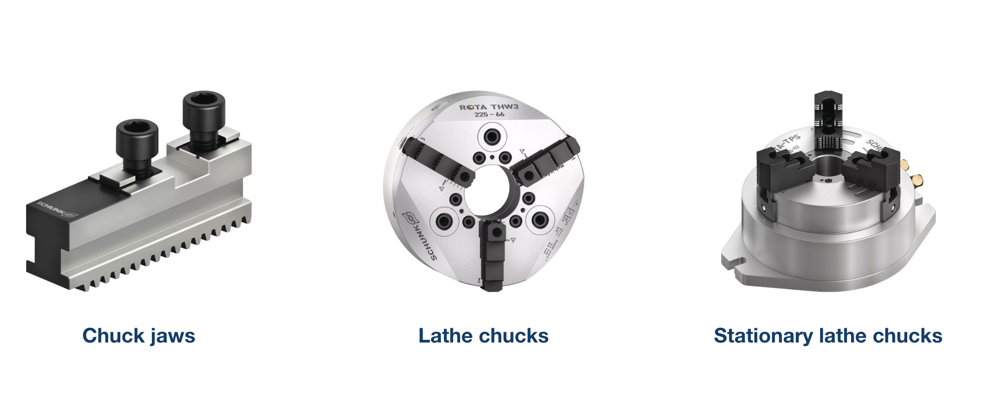
- Chucks: Used in CNC lathes, chucks (e.g., 3-jaw, 4-jaw, or collet chucks) grip cylindrical workpieces. They can be manually tightened or power-actuated.
- Clamps and Straps: Toggle clamps, strap clamps, or T-slot clamps secure irregularly shaped workpieces to machine tables.
- Technical Details: Mechanical systems rely on friction and compressive forces. The clamping force (F) is determined by the tightening torque (T) and the coefficient of friction (μ): F=Tr⋅μF = \frac{T}{r \cdot \mu}
F = \frac{T}{r \cdot \mu}where ( r ) is the radius of the screw or lever arm. High-precision vises may achieve forces up to 50 kN.
- Hydraulic Clamping:
- Uses pressurized hydraulic fluid to actuate clamping mechanisms, providing uniform and high force (up to 100 kN or more).
- Common in high-production CNC environments due to automation and quick setup.
- Example: Hydraulic vises or chucks in CNC machining centers, where a pump delivers fluid to pistons that close the jaws.
- Advantages: High force density, repeatability, and remote actuation.
- Challenges: Requires maintenance to prevent leaks and ensure consistent pressure (typically 50–200 bar).
- Pneumatic Clamping:
- Uses compressed air (typically 4–10 bar) to actuate clamps.
- Suitable for lighter workpieces or applications requiring rapid clamping/unclamping cycles.
- Example: Pneumatic chucks in automated CNC turning centers.
- Advantages: Fast response time and lower cost than hydraulic systems.
- Challenges: Lower clamping force compared to hydraulic systems, limiting use for heavy machining.
- Magnetic Clamping:
- Utilizes electromagnetic or permanent magnets to hold ferromagnetic workpieces (e.g., steel or iron).
- Common in surface grinding or milling of flat parts.
- Technical Details: Magnetic chucks generate holding forces proportional to the magnetic field strength (B) and contact area (A). Typical forces range from 100–150 N/cm².
- Advantages: No physical jaws, allowing full access to the workpiece surface.
- Challenges: Limited to ferromagnetic materials; risk of residual magnetism.
- Vacuum Clamping:
- Uses suction to hold non-ferromagnetic or thin workpieces (e.g., aluminum, composites, or sheet metal).
- Common in CNC routing or laser cutting.
- Technical Details: Vacuum pressure (typically 0.1–0.9 bar below atmospheric) creates a holding force proportional to the contact area:F=P⋅AF = P \cdot A
F = P \cdot Awhere ( P ) is the pressure difference and ( A ) is the contact area. - Advantages: Ideal for delicate or non-magnetic materials.
- Challenges: Limited force for heavy machining; requires a clean, flat surface for effective sealing.
- Zero-Point Clamping Systems:
- Modular systems that use standardized mounting points to achieve repeatable workpiece positioning with sub-micron accuracy.
- Example: Systems like Lang, Schunk, or Erowa use precision pins and chucks for quick-change setups.
- Advantages: Reduces setup time in high-mix, low-volume production.
- Technical Details: Clamping force is often hydraulic or pneumatic, with pull-in forces up to 60 kN per clamping point.
Applications in Metalworking and CNC
- CNC Milling: Vises, magnetic chucks, or zero-point systems hold workpieces for precise 3D contouring or slotting.
- CNC Turning: Chucks or collets secure cylindrical parts for rotational machining.
- Grinding: Magnetic or vacuum chucks ensure flatness and surface finish.
- Toolholding Integration: Toolholders (e.g., HSK, BT, or CAT standards) complement clamping by ensuring rigid tool-workpiece interaction. For example, HSK-A63 toolholders provide high stiffness (axial runout < 3 μm) to minimize vibration during high-speed machining.
Design Considerations
- Clamping Force: Must balance sufficient force to resist cutting forces (e.g., shear force Fs=σ⋅AF_s = \sigma \cdot A
F_s = \sigma \cdot A, where σ\sigma\sigmais material shear strength) without deforming the workpiece. - Workpiece Material: Hard metals (e.g., titanium) require higher clamping forces; soft materials (e.g., aluminum) need careful force control to avoid distortion.
- Accessibility: Clamping should not obstruct tool paths in multi-axis CNC machining.
- Thermal Effects: Machining heat can cause workpiece expansion, requiring adaptive clamping systems.
- Automation: Modern CNC systems integrate hydraulic/pneumatic clamps with PLCs (Programmable Logic Controllers) for automated loading/unloading.
Advanced Trends
- Smart Clamping: Sensors embedded in clamps monitor force, pressure, or position in real-time, integrating with Industry 4.0 systems for predictive maintenance.
- Adaptive Clamping: Systems that adjust force dynamically based on machining conditions, reducing deformation in thin-walled parts.
- Additive Manufacturing Integration: Clamping systems designed for hybrid manufacturing (e.g., combining CNC and 3D printing) to secure complex geometries.
Challenges
- Setup Time: Complex workpieces require custom fixtures, increasing setup costs.
- Deformation: Excessive clamping force can distort thin or delicate parts.
- Cost: Hydraulic and zero-point systems are expensive, though they improve throughput in high-volume production.
ConclusionWorkpiece clamping technology is a cornerstone of precision manufacturing in metalworking and CNC applications. By selecting the appropriate clamping method—mechanical, hydraulic, pneumatic, magnetic, vacuum, or zero-point—manufacturers can optimize for precision, speed, and safety. The choice depends on workpiece material, machining forces, production volume, and automation needs. Advanced systems with sensors and adaptive controls are increasingly common, aligning with the demands of modern CNC and Industry 4.0 environments.