What is Gripping Systems?

Gripping systems, also commonly referred to as workholding or clamping systems in technical literature, are critical components in metalworking, manufacturing, and CNC (Computer Numerical Control) machine tools. They are engineered devices or mechanisms designed to securely hold workpieces (raw material blanks or partially machined parts) in place during machining operations. This ensures stability, precision, and repeatability while minimizing vibrations, deflections, or displacements that could lead to inaccuracies, tool breakage, or safety hazards. In essence, gripping systems transform a static workpiece into a dynamically stable element within the machine tool’s coordinate system, enabling subtractive manufacturing processes like milling, turning, drilling, and grinding to occur with high efficiency.From a technical standpoint, gripping systems operate on principles of mechanical force application, often augmented by hydraulic, pneumatic, or electromagnetic actuation. They must accommodate the forces generated during machining—such as cutting forces (typically 1-50 kN depending on material and tool), centrifugal forces in rotary applications, and thermal expansions (up to 0.01-0.05 mm/°C in metals like steel or aluminum). Key performance metrics include clamping force (measured in Newtons or tons), gripping repeatability (often <0.005 mm), and cycle time for clamping/unclamping (ideally <5-10 seconds for high-volume production). These systems are integral to sectors like metalworking (e.g., fabrication of sheet metal or structural components), general manufacturing (e.g., automotive or aerospace parts), and CNC machinery (e.g., lathes, mills, or multi-axis centers), where they directly impact throughput, part quality, and operational costs.Below, I’ll explain gripping systems technically, focusing on their types, mechanics, integration with CNC tools, and applications in the specified sectors.Technical Principles and MechanicsGripping systems rely on controlled force distribution to achieve immobilization in multiple degrees of freedom (typically 3 translational and 3 rotational, or 6 DOF). The core function is to apply normal (perpendicular) and frictional (tangential) forces to counteract machining loads. For instance:
- Force Generation and Actuation:
- Mechanical Systems: Use levers, screws, or cams for manual or semi-automated clamping. Torque is applied via wrenches or motors, generating forces up to 10-20 kN. These are simple but limited in speed and repeatability.
- Hydraulic/Pneumatic Systems: Employ fluid or gas pressure (typically 5-20 MPa for hydraulics, 0.4-0.8 MPa for pneumatics) to drive pistons or cylinders. Clamping force F=P×AF = P \times A
F = P \times A(where ( P ) is pressure and ( A ) is piston area) can reach 50-100 kN, enabling rapid actuation (0.5-2 seconds). Feedback loops via pressure sensors ensure consistent force, preventing over-clamping that could deform soft metals like aluminum. - Electromagnetic or Vacuum Systems: For non-ferrous or delicate parts, electromagnetic chucks use magnetic fields (up to 1-2 Tesla) for attraction, while vacuum systems apply negative pressure (0.08-0.1 MPa) through porous tables. These provide uniform gripping without jaw marks but are limited to flat surfaces and lower forces (5-15 kN).
- Advanced Smart Systems: Integrate sensors (e.g., strain gauges or encoders) for real-time monitoring of clamping force and position, often interfaced with the CNC controller via PLC (Programmable Logic Controller) or IoT protocols. This allows adaptive gripping, where force adjusts based on spindle load feedback.
- Kinematics and Precision:
- Gripping systems must align the workpiece to the machine’s datum (reference points) with sub-micron accuracy. Repeatability is achieved through kinematic mounting (e.g., 3-2-1 principle: three points for location, two for rotation, one for clamping). Deflection under load is minimized using high-modulus materials like hardened steel (Young’s modulus ~200 GPa) or carbide jaws.
- In dynamic applications, such as high-speed machining (spindle speeds >10,000 RPM), systems incorporate vibration damping via elastomeric inserts or active control (piezoelectric actuators) to maintain tolerances of ±0.001-0.01 mm.
- Integration with CNC Controls:
- CNC machines use G-code (e.g., M10/M11 for clamp/unclamp) and M-code to automate gripping sequences. The system interfaces with the CNC’s servo drives and encoders for closed-loop feedback, ensuring the workpiece position is verified post-clamping (e.g., via probe touch-off). In multi-axis CNC (4-5 axes), rotary grippers or trunnions allow reorientation without manual intervention, reducing setup time by 50-70%.
Types of Gripping SystemsGripping systems are categorized based on workpiece geometry, operation type, and sector needs. Here’s a technical comparison:
| Type | Description & Mechanics | Typical Clamping Force | Applications in Sectors | Advantages/Disadvantages |
|---|---|---|---|---|
| Vise/Jaw Clamps | Parallel or self-centering jaws (steel or soft inserts) actuated by screw or hydraulic mechanisms. Jaws apply opposing forces for cubic/prismatic parts. | 5-50 kN | Metalworking (milling flats), CNC mills/lathes for automotive brackets. | High rigidity; simple. / Limited to rectangular shapes; jaw marks on finishes. |
| Collets/Chucks | Conical sleeves (collets) or 3/4-jaw chucks that radially compress via drawbar (axial pull of 10-30 kN). Often spring-loaded for quick release. | 10-100 kN | CNC turning (bar stock in lathes), manufacturing of shafts/gears. | Excellent concentricity (<0.005 mm TIR); fast cycles. / Restricted to cylindrical parts. |
| Fixturing Plates/Tombstones | Modular grids with T-slots or dowel pins for custom setups. Uses clamps, straps, or edge grippers for irregular shapes. | 2-20 kN per point | CNC multi-part production in manufacturing; aerospace components on vertical mills. | Versatile for batch runs; repeatable setups. / Higher setup time (10-30 min). |
| Bar Pullers/Grippers | Automated fingers (e.g., coolant-actuated pistons in stainless steel) that grip and advance bar stock. Self-adjusting for diameters 3-80 mm. | 1-5 kN | CNC lathes in metalworking for high-volume turning; e.g., Grippall™ systems for automation. | Reduces manual intervention; integrates with coolant (0.5-7 bar pressure). / Limited to linear feeding. |
| Dovetail or Zero-Point Systems | Dovetail fixtures with minimal contact (e.g., 20-30% surface area) using quick-release balls or pneumatics. Provides 5-sided access. | 10-40 kN | Advanced CNC (5-axis) in manufacturing; medical implants or marine parts. | Low-profile (reduces interference); high precision. / Requires precise machining of dovetails. |
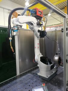
| Robotic/End-of-Arm Tooling (EOAT) | Servo-driven grippers with parallel fingers or adaptive pads, controlled via CNC-linked robots (e.g., 6-DOF arms). Force sensing via torque feedback. | 5-50 kN | Automated manufacturing lines; loading/unloading in CNC cells for sheet metal. | Flexible for varied parts; Industry 4.0 integration. / Higher cost; needs calibration. |
Applications in Metalworking, Manufacturing, CNC Machine Tools, and Machinery Sectors
- Metalworking Sector: Gripping systems secure sheet metal or billets for processes like plasma/laser cutting, punching, or bending. For example, in CNC plasma cutters, magnetic or vacuum chucks hold thin sheets (0.5-10 mm thick) to prevent warping under thermal loads (up to 1000°C). Hydraulic vises in fabrication ensure edge alignment for shearing, maintaining tolerances of ±0.1 mm. Challenges include handling heat-treated metals (e.g., titanium alloys with hardness >40 HRC), where soft jaws prevent galling.
- Manufacturing Sector: In high-volume production (e.g., automotive or electronics), modular fixturing enables just-in-time setups for parts like engine blocks or housings. Zero-point systems reduce changeover time from hours to minutes, supporting lean manufacturing. For composites or hybrid materials, adaptive grippers use compliant mechanisms (e.g., compliant fingers with deflection <0.1 mm) to avoid damage.
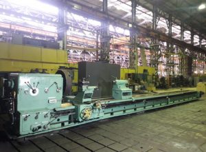
- CNC Machine Tools Sector: On lathes, collet chucks or bar feeders grip rotating workpieces at speeds up to 5000 RPM, with dynamic balancing to limit vibrations (<0.01 mm amplitude). In milling centers (3-5 axis), tombstone fixtures hold multiple parts, optimizing tool paths via CAM software. Closed-loop integration with encoders ensures post-clamping alignment, critical for multi-setup operations where cumulative errors must stay <0.02 mm.
- Machinery Sector: For heavy machinery production (e.g., gears or turbines), large hydraulic chucks (up to 200 kN) on horizontal machining centers grip oversized components (diameters >500 mm). In automated lines, robotic grippers with vision systems (e.g., cameras for edge detection) handle irregular castings, integrating with CNC via Ethernet/IP for synchronized loading.
Benefits and ConsiderationsTechnically, gripping systems enhance CNC efficiency by reducing cycle times (up to 30-50% via automation), improving surface finishes (Ra <1.6 µm), and minimizing scrap rates (<1%). However, selection depends on material properties (e.g., ductility of aluminum vs. brittleness of cast iron) and process forces. Maintenance involves regular calibration of actuators and jaw wear checks to sustain performance. In Industry 4.0 contexts, AI-optimized gripping (predictive force adjustment) is emerging for zero-defect manufacturing.Overall, gripping systems are the foundational enablers of precision in these sectors, bridging design intent (from CAD) to physical output while adapting to the evolving demands of high-speed, multi-material machining.