What is the Rotabloc Energy Storage Unit, and how can this simple UPS system be configured to provide the required level of redundancy and flexibility for your facility?
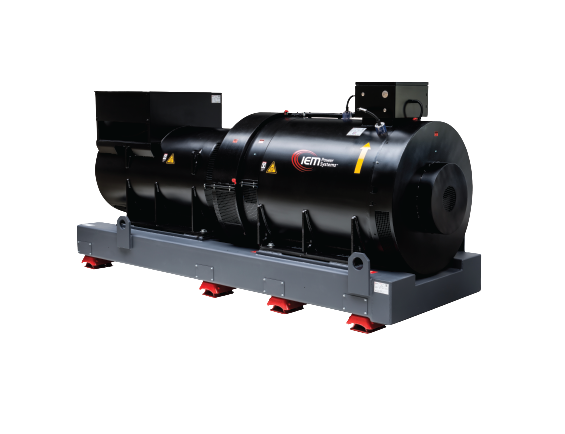
The Rotabloc Energy Storage Unit is a core component of a rotary uninterruptible power supply (UPS) system developed by Industrial Electric Mfg. (IEM) Power Systems. It functions as a kinetic energy storage device, primarily using a high-inertia flywheel to store electrical energy in the form of rotational kinetic energy, rather than relying on chemical batteries or fragile electronic components. This makes it a robust, low-maintenance alternative to traditional static UPS systems, particularly suited for industrial, data center, and critical infrastructure applications where high reliability and long-term durability are essential.Technical Principles and OperationAt its core, the Rotabloc operates on the principle of converting electrical energy to mechanical energy for storage and back to electrical energy for discharge. The stored energy ( E ) in the flywheel is given by the kinetic energy formula:
E=12Iω2E = \frac{1}{2} I \omega^2E = \frac{1}{2} I \omega^2 where ( I ) is the moment of inertia of the flywheel (dependent on its mass distribution and geometry), and
ω\omega\omega is the angular velocity (related to rotational speed). Unlike high-speed flywheels in other systems (which can exceed 10,000 RPM and require active magnetic bearings), the Rotabloc uses a low-speed shaft design (typically under 1,800 RPM for 50/60 Hz systems), which significantly extends bearing life (often exceeding 25 years with minimal maintenance) and reduces mechanical stress.Key technical components and mechanisms include:
- Flywheel Rotor: A robust, steel-based rotor (over 99.97% recyclable) that stores energy. Its design optimizes mass distribution to maximize ( I ) while minimizing material stress, allowing for safe operation at variable speeds without the need for vacuum enclosures or exotic materials.
- Patented Electromagnetic Coupling: This is a frictionless, maintenance-free mechanism for energy transfer. It uses electromagnetic fields to couple the flywheel to the motor-generator without physical contact, avoiding wear from clutches or gears. During discharge, the coupling induces current in the generator windings via Faraday’s law of electromagnetic induction, converting rotational energy back to AC electrical power.
- Drive Motor: An AC induction or synchronous motor that accelerates the flywheel during charging. It employs dynamic speed control, a proprietary algorithm that automatically adjusts ω\omega
\omegato match the instantaneous power demand of the load. This prevents over-speeding (which wastes energy and accelerates wear) and optimizes efficiency by balancing energy input/output. For example, under light load, the flywheel speed is reduced to conserve energy, achieving up to 97% system efficiency. - Variable Frequency Drive (VFD): Integrated to control the motor’s speed and torque, ensuring precise synchronization with the input utility power (e.g., 50/60 Hz, 400-2000 kVA ratings, scalable to 50 MW+). The VFD also handles recharging from the utility or backup generator by ramping up the flywheel speed gradually.
- Absence of Fragile Elements: Unlike static UPS systems (e.g., double-conversion with IGBT inverters) or other rotary designs, the Rotabloc avoids power electronics (e.g., capacitors prone to failure), electrochemical batteries (subject to degradation and thermal runaway), active magnetic bearings (which require constant power), and mechanical clutches (which introduce friction losses). This results in a mean time between failures (MTBF) far exceeding 1 million hours and operational life >25 years.
The unit provides short-term ride-through power (typically 10-30 seconds at full load, configurable based on flywheel size and speed) for “No-Break” critical loads during utility outages, while filtering power quality issues like voltage sags, spikes, harmonics, and flickers in normal operation. Power ratings range from 400-2000 kVA (320-1600 kW), with low-voltage (LV, e.g., 480V) or medium-voltage (MV, e.g., 11 kV) configurations.In a basic setup, the Rotabloc acts as the energy buffer in a Diesel Rotary UPS (DRUPS) system:
- Normal Mode: Utility power drives the motor via the VFD, maintaining flywheel speed and supplying conditioned power to the load through the electromagnetic coupling and generator.
- Outage Mode: The flywheel’s inertia sustains rotation, delivering power via the generator. A backup diesel generator starts (electrically synced, no mechanical coupling) and recharges the flywheel once online, ensuring seamless transition without load interruption.
- Recovery Mode: Utility restoration recharges the flywheel, gradually offloading the generator.
This electrically coupled design allows the generator to be located remotely, tested independently, and operated without mechanical wear, enhancing overall system reliability.The Rotabloc as a Simple UPS System (RBT Configuration)The Rotabloc Energy Storage Unit forms the foundation of the RBT UPS System, a complete rotary UPS solution that integrates the Rotabloc with power cabinets, control systems, and switchgear. The RBT extends the basic storage unit into a full UPS by adding:
- Power and Control Cabinets: These include rectifiers for DC excitation (if synchronous generator), inverters for output conditioning, and a human-machine interface (HMI) for monitoring.
- Switchgear: Low/medium-voltage input/output breakers for utility and generator integration.
- Integration Software: Links components into a unified system, compatible with building management systems (BMS) for remote monitoring of parameters like voltage, frequency, temperature, and energy levels.
The RBT is described as “simple” due to its mechanical-electrical hybrid design, which minimizes electronic complexity and points of failure compared to static UPS systems. It provides continuous protection against 99% of power disturbances, with configurable bypass modes for maintenance (e.g., static or maintenance bypass to utility/generator without interrupting the load).Configuring the RBT UPS System for Redundancy and FlexibilityThe RBT’s modular architecture allows it to be configured as a scalable, redundant UPS system tailored to a facility’s critical load requirements, availability targets (e.g., 99.999% uptime for Tier III/IV data centers), and growth needs. Redundancy ensures no single point of failure (N+1 or higher), while flexibility supports customization for load types, voltage levels, and integration. Configurations are achieved through parallel operation, system integration, and optional features, with total cost of ownership (TCO) benefits from high efficiency and low maintenance.Achieving RedundancyRedundancy in the RBT is primarily implemented via parallel configurations, where multiple Rotabloc/RBT units share the load and provide failover. This is more reliable than single-module setups (N configuration, MTBF ~2.6M hours) and avoids the inefficiency of fully duplicated systems (2N). Key approaches:
- N+1 Parallel Redundancy (Most Common for RBT):
- Setup: Deploy ( N ) RBT modules to handle the full critical load (e.g., N=2 for a 1 MW load, each rated 500 kW), plus 1 redundant module. All modules connect to a common parallel bus (via switchgear) that distributes power to the load. Synchronization is managed by the control software, ensuring phase-locked operation (e.g., <4 ms transfer time).
- Technical Operation: In normal mode, load is shared equally (e.g., 50% per active module). If one module fails (e.g., due to bearing anomaly or VFD fault), it isolates automatically via breakers, and the remaining N modules ramp up to 100% capacity (or the +1 takes over). The electromagnetic coupling and dynamic speed control allow seamless load redistribution without voltage/frequency dips.
- Benefits for Facility: Provides fault tolerance for maintenance (e.g., annual flywheel inspection) or failures, achieving MTBF >10M hours. Excess generator capacity can protect “Short-Break” essential loads (e.g., non-critical HVAC) during outages.
- Scalability: Start with 1 module for basic protection; add parallels for redundancy as load grows. Supports up to 50 MW+ by stacking units.
- Distributed Redundancy (e.g., 2N+1 or Isolated Redundant):
- Setup: For higher resilience, use a 2N architecture (two independent RBT systems, A and B sides) with +1 redundancy per side. Each side feeds dual-corded loads via static transfer switches (STS). A “catcher” module (redundant RBT) connects to STS secondaries to back up primaries.
- Technical Operation: A-side and B-side operate in parallel but isolated; failure of one side transfers load via STS (<10 ms). The +1 ensures N+1 within each side. Dynamic speed control optimizes each flywheel independently, and the control system monitors bus voltage/frequency for auto-sync.
- Benefits: Handles concurrent maintenance (e.g., test one side while the other runs) and multi-fault scenarios. Ideal for facilities with segmented loads (e.g., separate server racks).
- Integrated DRUPS for Extended Redundancy:
- Combine multiple RBT units with redundant generators and switchgear in a fully integrated package. Breakers (e.g., N1 for utility, G1 for generator) ensure automatic failover. Redundancy extends to controls (dual HMIs) and power paths, with BMS integration for predictive monitoring (e.g., vibration analysis on flywheel bearings).
In all cases, redundancy is quantified by availability: N+1 yields ~99.999% uptime, assuming 10-30s flywheel bridge time covers generator start (10-15s).Achieving FlexibilityThe RBT’s design emphasizes adaptability without compromising simplicity:
- Modular Power Ratings and Scalability:
- Units are available in discrete sizes (400-2000 kVA), allowing mix-and-match for exact load matching (e.g., parallel 500 kVA units for 1.5 MW). Expand by adding modules to the bus, supporting future growth up to 50 MW without full system replacement.
- Voltage and Configuration Options:
- LV/MV Support: Configure for 480V LV or 11 kV MV, with transformers for stepping. Isolated parallel systems (no common neutral) for grounding flexibility.
- Containerization/Rental: Modules can be housed in standard containers for mobile/deployable setups or rented for temporary redundancy.
- Bypass and Load Segregation: Configurable static/maintenance bypass for No-Break (critical, e.g., servers) vs. Short-Break (essential, e.g., lighting) loads. Optional VFD tuning for short interruptions (e.g., 100 ms sags).
- Integration and Customization:
- Control Software: Programmable HMI/BMS interface for custom thresholds (e.g., speed setpoints, alarm levels). Supports API for facility-wide automation.
- Efficiency Tuning: Dynamic speed control configurable to prioritize energy savings (lower speed under light load) or max output (higher speed for peaks).
- Environmental Adaptability: Robust for harsh environments (IP-rated enclosures), with low embodied energy (steel/copper construction) for green facilities. Turnkey solutions include full testing/integration, reducing on-site risks.
- Economic and Operational Flexibility:
- Lower CapEx than 2N static systems due to shared components; OpEx savings from >97% efficiency and minimal maintenance (no battery replacement). Configurable for TCO optimization, e.g., remote generator placement to save space.
To implement for a specific facility, assess load profile (e.g., via power audit), availability needs (e.g., N+1 for 99.999%), and constraints (space, voltage). IEM provides simulation tools to model configurations, ensuring the system delivers required redundancy (e.g., via parallel N+1) and flexibility (e.g., modular scaling). This results in a tailored, reliable UPS that outperforms traditional systems in longevity and sustainability.