What is Mesh Welding System?
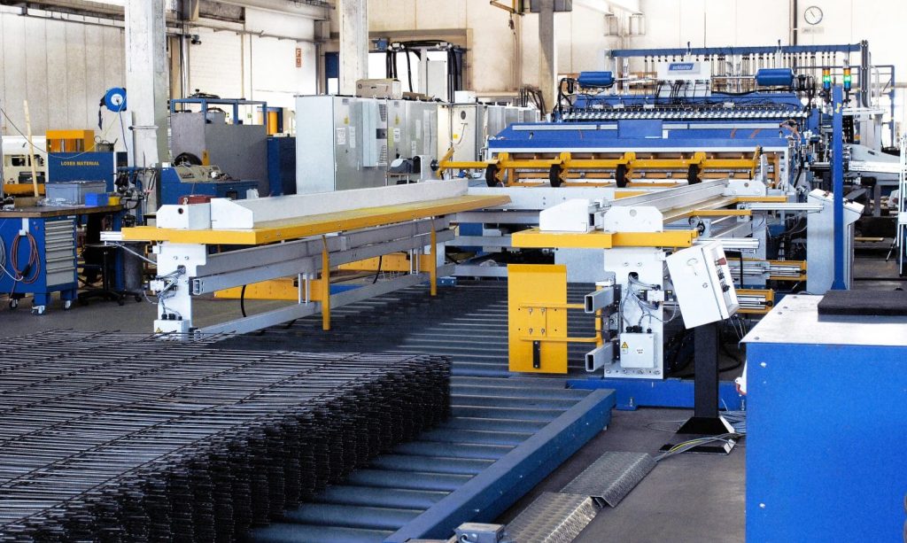
A mesh welding system (also called a wire mesh welding line or reinforcing mesh welding machine) is an automated electromechanical production system designed to weld intersecting wires into a grid or mesh pattern, forming sheets or rolls used in construction, industrial reinforcement, fencing, and other structural applications.
Let’s break it down thoroughly — from its mechanical design and working principle, through electrical control and welding technology, to applications and variants.
1. Purpose and Function
A mesh welding system joins longitudinal and cross wires at their intersection points by resistance spot welding, forming a rigid, dimensionally precise wire mesh.
It automates all key stages:
- Feeding straightened wires (from coil or pre-cut)
- Positioning longitudinal and cross wires at programmed spacings
- Applying electrical current and pressure via welding electrodes
- Advancing the mesh sheet or roll step by step
- Cutting to length or rolling finished mesh
Essentially, it’s a high-throughput, precision resistance welding line optimized for multiple parallel welds per cycle.
2. System Architecture & Main Components
A complete mesh welding system typically comprises:
| Subsystem | Technical Description |
|---|---|
| Wire Pay-off & Straightening Units | Feed longitudinal and cross wires from coils; straightened and cut automatically using rotating dies or servo straighteners. |
| Wire Feeder & Positioning Mechanism | Accurately positions longitudinal wires in parallel on a bed; cross wires are placed perpendicularly via automatic feeding grippers or flying shear systems. |
| Welding Portal / Electrode Assembly | Houses upper and lower copper electrodes aligned to each intersection row; often pneumatically or servo-actuated to apply pressure. |
| Welding Transformers / Power Units | Deliver high current (typically 30–150 kA) at low voltage (1–5 V) for very short welding pulses (20–200 ms). Multiple transformers operate in parallel. |
| Current Distribution Busbars | Heavy copper bus systems distribute current evenly to electrode pairs; designed to minimize inductive losses. |
| Welding Control System | Synchronized timing control for each electrode pair; manages current, voltage, and pressure per weld point. Modern systems use PLC + IGBT / MFDC inverter controls. |
| Mesh Indexing & Step Feeding Mechanism | After each weld cycle, servo-driven rollers or step clamps advance the mesh precisely by the programmed pitch. |
| Cutting / Stacking / Rolling Unit | Finished meshes are either cut to length by shear blades and stacked, or rolled automatically for storage or shipment. |
| Human–Machine Interface (HMI) / PLC Control Panel | Operators program mesh dimensions, wire spacing, welding energy, and production count. |
| Safety & Monitoring Systems | Light curtains, interlocks, current sensors, and temperature monitoring to ensure consistent weld quality and operator safety. |
3. Working Principle – Resistance Welding of Mesh Intersections
The core principle is resistance spot welding applied simultaneously across many intersections.
Process steps:
- Positioning: Longitudinal wires lie on the lower electrode line; cross wires drop onto them.
- Clamping: The upper electrodes descend, clamping the intersection points.
- Welding current: A large current flows through each contact, generating localized Joule heat (Q = I²Rt) which melts the interface between wires.
- Pressure hold: Current stops; pressure remains to forge the molten metal into a solid weld nugget.
- Release & advance: Electrodes lift; the mesh advances by one pitch to weld the next row.
Because all electrode pairs fire simultaneously, a single stroke welds dozens of intersections in under one second.
4. Control Technology & Synchronization
Modern mesh welding systems rely heavily on digital control:
- PLC / CNC Controller: Coordinates timing between wire feed, electrode descent, current pulse, mesh indexing.
- MFDC (Medium Frequency Direct Current) Inverter Welding: Converts 3-phase AC into ~1 kHz DC pulses for higher efficiency, reduced electrode wear, and precise energy control.
- Servo Motors: Replace pneumatic cylinders for wire positioning, electrode lift, and mesh indexing — improving repeatability.
- Proportional Air Regulators / Hydraulic Servos: Maintain constant welding pressure across electrodes.
- Feedback Sensors: Monitor weld current, voltage, electrode force, temperature — feeding back to controller for adaptive energy adjustment.
Advanced versions allow independent welding control per electrode (selective welding), letting you produce variable mesh geometries on the same machine.
5. Technical Parameters (Typical Ranges)
| Parameter | Typical Range | Notes |
|---|---|---|
| Wire diameter | 2 – 12 mm | Construction mesh uses 4–10 mm; fine mesh uses 1–3 mm |
| Wire spacing (pitch) | 25 – 300 mm | Programmable longitudinal & cross spacing |
| Welding current | 30 – 150 kA | Depending on wire thickness and alloy |
| Welding voltage | 1 – 5 V | Low voltage, high current |
| Welding time | 10 – 200 ms | Controlled by solid-state timer |
| Welding force per electrode | 500 – 5,000 N | Dependent on wire gauge |
| Production speed | Up to 120 cross-wires/min or > 100 sheets/hr | High-speed automated lines can exceed 150 cross wires/min |
| Accuracy | ±0.2 mm to ±1.0 mm per pitch | Servo-controlled |
6. Variants of Mesh Welding Systems
| Type | Application | Characteristics |
|---|---|---|
| Construction / Reinforcing Mesh Line | Concrete reinforcement (rebar mesh) | Heavy-duty; handles 4–12 mm wires; welded sheets ~6 × 2.4 m |
| Light Wire / Fencing Mesh Line | Fences, cages, industrial racks | Lighter wires (2–5 mm); often produce rolls |
| Pre-cut Wire Mesh Welder | Pre-straightened and cut wires fed automatically | High accuracy; ideal for smaller batches |
| Coil-Fed Continuous Mesh Line | Feeds from coil stock with automatic straightening and cutting inline | Fully automated, high-speed |
| Variable Pitch / Programmable Mesh Welder | Custom / architectural meshes | Servo positioning for arbitrary wire spacing |
| Stainless / Non-Ferrous Mesh Welder | Special alloys (Cu, Al, SS) | Requires adaptive current control due to different resistivity |
7. Quality Control & Testing
Because mesh strength depends on weld integrity, QC is critical:
- Weld Nugget Test / Peel Test: Physically separating welded intersections to ensure fusion area size.
- Shear / Tensile Test: Confirms mechanical strength meets standards (e.g. ISO 15630, ASTM A1064).
- Dimensional Inspection: Automatic laser or camera measurement of pitch and squareness.
- Electrical Monitoring: Measures actual current, voltage, and resistance per weld to ensure uniform energy delivery.
- Data Logging: Modern PLC systems record every weld parameter for traceability.
8. Typical Industrial Applications
Mesh welding systems are used wherever wire grids are required:
- Construction reinforcement mesh (for concrete slabs, roads, precast panels)
- Fencing and security mesh (galvanized or PVC-coated)
- Industrial racks, cages, and shelving
- Automotive parts (seat frames, supports)
- Pipe reinforcement (spiral welded mesh)
- Heat exchanger grids
- Architectural / decorative mesh panels
9. Material Considerations
| Material | Welding Characteristics |
|---|---|
| Low-carbon steel | Excellent weldability; most common |
| Galvanized steel | Requires proper current and pressure to avoid zinc vaporization |
| Stainless steel | Needs higher current and short welding time to avoid discoloration |
| Aluminum / Copper | High conductivity makes resistance welding more difficult; special electrodes and controls used |
10. Advantages of Modern Mesh Welding Systems
- High production rate – multiple welds per cycle
- Precision – consistent pitch and square geometry
- Reduced manpower – fully automatic operation
- Energy efficiency – MFDC inverter power reduces heat loss
- Customization – programmable mesh geometry (different spacings, wire diameters)
- Traceability & data logging – digital process monitoring
- Low maintenance – modular electrode design and easy access
- Safety – enclosed zones and interlocked guarding
11. Common Issues & Maintenance Points
- Electrode wear or contamination – causes inconsistent welds; requires regular dressing or replacement
- Loose busbar connections – can overheat and cause current imbalance
- Uneven wire feed or misalignment – leads to poor weld registration or off-pitch mesh
- Dirty wire surface – high resistance, spatter, or incomplete weld
- Cooling circuit blockage – overheats electrodes
- PLC / Sensor faults – cause synchronization errors between feed and weld cycles
Preventive maintenance (lubrication, alignment, calibration, cleaning) ensures reliable operation.
12. Example Technical Workflow (Simplified)
- Longitudinal wire feeding → wires laid on electrode bed
- Cross wire cutting & feeding → drops cross wire onto longs
- Electrode downstroke + current pulse → welds one row of intersections
- Electrode lift + mesh indexing → moves mesh forward one pitch
- Repeat cycle until desired length
- Automatic shearing / rolling → output as sheet or roll
This cycle repeats continuously at up to 100+ strokes/min on high-speed lines.
13. Leading Manufacturers
Some globally recognized producers of mesh welding systems include:
- Schlatter Group (Switzerland)
- EVG (Austria)
- MBK Maschinenbau (Germany)
- TJK Machinery (China)
- Jiaoyang Welding (China)
- Eurobend (Greece)
- Maillefer (Switzerland) — in broader wire / cable equipment domain, offers coiling, extrusion, and winding systems
14. Summary
A mesh welding system is a high-precision automated resistance-welding production line that:
- Feeds and positions longitudinal and cross wires automatically
- Welds them at intersections using simultaneous spot welding
- Produces sheets or rolls of uniform mesh
- Is controlled by advanced PLC / inverter systems for speed, accuracy, and energy efficiency
In essence, it transforms loose wire into a rigid, dimensionally stable product that serves as a fundamental building block for construction, fencing, reinforcement, and industrial applications.