18/10/2025
What is Image Dimension Measurement System Model incorporating programmable ring-illumination/light probe unit?

An image-dimension measurement system incorporating a programmable ring-illumination / light-probe unit is a high-precision optical metrology instrument designed for rapid and accurate measurement of part dimensions. Below is a technical explanation of its key components, how they work, and what to look for when assessing such a system.
Core Functional Principle
The system combines three main technologies:
- High-resolution camera with telecentric optics – captures a distortion-free image of the part’s profile.
- Programmable ring-illumination – a lighting system that can change angle, intensity and pattern of illumination around the part to enhance edge detection under varying surface conditions.
- Light probe unit – a small optical or contact probe that complements the image measurement by allowing measurement of features that are difficult to capture with purely top-view imaging (e.g., depths, recessed features, height differences).
Technical Breakdown of Components & Operation
• Telecentric optics + camera
- The telecentric lens ensures that magnification does not change with object distance; the result: sharp measurement edges and minimal distortion.
- A high-pixel monochrome (or colour) CMOS sensor is typically used, enabling measurement resolution down to sub-micron levels (for example in some models, ~0.1 µm display units).
- The XY-stage (and sometimes Z-stage) allows the part to be positioned precisely and multiple features to be measured in one fixture.
• Programmable ring-illumination
- The “ring” refers to lighting arranged in a circular configuration around the imaging lens or stage. “Programmable” means you can adjust or switch between modes (e.g., full ring, slit-ring, multi-angle segments) to adapt to part surface, reflectivity, transparency or geometry.
- The illumination modes typically include:
- Transparent illumination (from beneath) for silhouette measurement.
- Ring or slit ring illumination from above or at oblique angles for enhanced contrast on edges.
- Multi-angle segmented ring illumination which enables switching lighting directions to reduce shadows or glare.
- Why it matters: Part surfaces vary (coated, shiny, transparent, textured) and lighting greatly affects measurement accuracy. Programmable illumination improves repeatability and reduces operator setup time.
• Light-probe unit
- This is a small probe (optical or very low force contact) that measures features not easily resolved by a top-view image, such as height differences, recessed features, or depths.
- The probe might have a small diameter (for example Ø3 mm) and a low measuring force (~0.015 N) so as not to deform the part.
- It allows the system to measure both 2D (via imaging) and certain 3rd-dimension (height/depth) features in a single setup, increasing versatility.
Typical Measurement Performance Specifications
When evaluating such a system you’ll encounter parameters like:
- Minimum display unit: e.g., 0.1 µm or 0.05 µm depending on model.
- Repeatability (without stage movement) and with stage movement (for example ±1 µm or ±2 µm).
- Measurement accuracy expressed as ±(a + b × L) µm, where L is the measurement length in mm.
- For the light-probe unit: measurable area for probe XY, maximum measurement depth, probe diameter, repeatability etc.
- Stage size / measurement field – for example 200 mm × 200 mm for one variant.
Practical Application Insights
- Because of the programmable illumination, these systems are very good for parts with mixed surfaces (shiny, transparent, textured). Changing light modes ensures edges are cleanly detected rather than lost in glare.
- The light-probe unit allows you to handle parts with complex geometry—e.g., you might use imaging for outer dimensions, and the probe for height or depth of features.
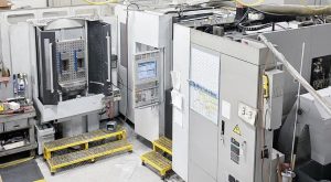
- Such systems are often used in production inspection (high-throughput) rather than just the metrology lab, because they allow rapid measurement of multiple features in one fixture. References note users measuring many parts quickly and repeating measurement cycles.
- However, limitations exist: The accuracy for very complex 3-D geometries or very large parts may still require a full-CMM rather than an image-dimension system. Some users report this in practice.
What to Check When Considering Purchase or Application
- Confirm the measurement field / stage size is adequate for your part size.
- Check the illumination modes present, and whether they cover your surface types.
- Verify the light-probe specification: diameter, force, depth capability—will it cover your depth/height features?
- Review accuracy specs (repeatability, systematic error, measurement length formula) to ensure they meet your tolerance requirements.
- Check whether the system is calibrated and traceable; look for calibration certificate.
- Test in your real-world part scenario: part surface finish, fixturing, lighting environment in your plant (ambient light may affect measurement).
- Consider software capabilities (feature recognition, batch measurement, data export) and ease of programming.
- Understand system limitations: for example, if your parts are extremely large, or very complex 3D free-form surfaces, an image-dimension system may not suffice.