What is Hydraulic Travelling Head Cutting Press Machine?
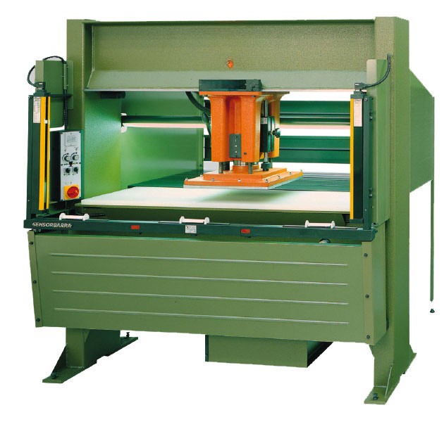
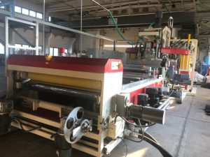
A Hydraulic Travelling Head Cutting Press Machine, often referred to as a hydraulic traveling head die cutting press or clicker press, is a specialized industrial machine designed for precision die cutting operations. It is primarily used to shear or blank shapes from sheet or roll materials using custom steel rule dies. The “travelling head” refers to the movable upper platen (or beam) that traverses horizontally across a larger worktable, allowing operators or automated systems to position the die accurately over the material. This design enhances accessibility and efficiency compared to fixed-head presses, making it suitable for medium- to high-volume production.While commonly associated with softer materials like leather, rubber, foam, textiles, and plastics in industries such as footwear, automotive gaskets, and packaging, the machine can be adapted for the sheet metal sector. In sheet metal applications, it is used for blanking (cutting out flat shapes) or trimming thin-gauge sheet metal (typically up to 2-3 mm thick, such as mild steel, aluminum, or non-ferrous alloys) that has been pre-softened or annealed to reduce hardness. For harder metals, it may require custom high-strength dies and higher tonnage, but it is not ideal for heavy-duty metal forming like deep drawing or punching thick plates, where dedicated hydraulic presses or CNC turret punches are preferred. The machine’s hydraulic system provides controlled force to ensure clean cuts without excessive deformation.Technical Components and Working PrincipleThe machine operates on hydraulic principles, leveraging Pascal’s law, which states that pressure applied to a confined fluid is transmitted equally in all directions. This allows a small input force to generate a large output force for cutting. Below is a breakdown of the key technical components and their functions:
- Frame and Structure:
- Constructed from high-grade steel (e.g., IS 2062 Grade B or equivalent) for rigidity and stability, often with a four-post or C-frame design to minimize deflection under load.
- Worktable (bed): Typically rectangular, ranging from 600 mm x 1,500 mm to 1,000 mm x 2,000 mm or larger, made of hardened steel or provided with a cutting board (e.g., polyurethane or hardwood) to support the material and absorb impact. The bed size determines the maximum sheet or roll width processable.
- Head size: The travelling head (upper beam) is usually square or rectangular, 400 mm x 400 mm to 800 mm x 800 mm, allowing it to cover dies up to that dimension.
- Hydraulic System:
- Pump and Reservoir: An electric motor-driven gear or vane pump circulates hydraulic oil (e.g., ISO VG 46) from a reservoir (20-100 liters capacity) to generate pressure up to 300 bar (approximately 30 MPa).
- Cylinders: Single or dual hydraulic cylinders (bore diameter 100-250 mm) mounted on the head provide the ram (platen) motion. The ram descends vertically with a stroke length of 100-200 mm.
- Valves and Controls: Directional control valves (e.g., solenoid-operated) manage upstroke (retraction) and downstroke (cutting). Pressure relief valves prevent overload, while flow control valves regulate speed. Modern machines use proportional valves for variable speed control.
- Power and Force: Tonnage ranges from 10-50 tons for entry-level models to 100-150 tons for industrial variants (1 ton ≈ 8.9 kN). Force (F) is calculated as F = P × A, where P is hydraulic pressure and A is the cylinder piston area. For example, a 200 mm diameter cylinder at 250 bar yields about 80 tons of force.
- Energy efficiency: Some models feature patented low-HP motors (e.g., 3-7.5 kW) that only activate during the cutting cycle, reducing power consumption by up to 75% compared to continuous-run systems.
- Travelling Mechanism:
- The head is mounted on a carriage that moves linearly along rails or tracks via manual push-buttons, pneumatic cylinders, or servo motors in automated versions.
- Traverse distance: Up to 1,000-1,500 mm, enabling the head to “travel” over a large bed for die placement. In manual models, operators use two-hand anti-tie-down controls with a 0.3-second delay for safety (per OSHA/CE standards).
- Automation options: PLC (Programmable Logic Controller) or CNC integration for multi-axis control, including head rotation (up to 360°) for optimal nesting (arranging dies to minimize waste). Touch-screen interfaces allow program storage for repeat jobs, with repeatability of ±0.03 mm.
- Die and Material Handling:
- Dies: Steel rule dies (perimeter blades, 1-2 mm thick) are placed on the material. For sheet metal, hardened dies (e.g., 60 HRC) with sharpened edges are used to handle metallic shear strength.
- Feeding: Manual sheet placement, pinch rollers for rolls, or conveyor systems for automation. Illumination (LED spotlights) aids visibility.
- Cutting Board: Replaceable to maintain flatness; wear is reduced by precise head positioning.
Working Principle (Step-by-Step)The process follows a hydraulic power cycle, ensuring even pressure distribution for uniform cut depth:
- Setup: Material (e.g., 1 mm aluminum sheet) is laid on the bed. The die is positioned on the material.
- Head Positioning: The travelling head is moved over the die using controls. Proximity sensors or encoders ensure alignment (accuracy ±0.1 mm).
- Cycle Initiation: Two-hand buttons activate the system. The hydraulic pump pressurizes oil, extending the cylinder to lower the ram at 50-100 mm/s.
- Cutting Phase: The ram applies full tonnage, shearing the material along the die edges. Dwell time (0.5-2 seconds) ensures complete penetration. Shear force required depends on material thickness (t), width (w), and shear strength (τ): F_shear ≈ τ × t × w (e.g., for mild steel τ ≈ 300 MPa).
- Retraction: Pressure is released, and the ram rises hydraulically (faster upstroke for efficiency). The head returns to a home position.
- Ejection and Repeat: Cut parts are removed; waste skeleton is cleared. Cycle time: 5-20 seconds per cut, depending on automation.
Safety features include light curtains, emergency stops, and overload protection to prevent hydraulic surges.Application in the Sheet Metal SectorIn the sheet metal industry, this machine is valued for its versatility in low- to medium-force blanking operations, particularly for prototyping or small-batch production of components like washers, brackets, shims, or electrical enclosures from thin sheets. It excels where precision nesting reduces scrap (up to 20-30% material savings via rotation) and where access to large sheets (up to 2 m wide) is needed without full automation costs.
- Suitable Materials and Limits: Thin non-ferrous (aluminum, copper) or annealed ferrous sheets (mild steel up to 2 mm). For harder metals, pre-annealing or lubrication is required to lower cutting resistance. Not recommended for thicknesses >3 mm or high-strength steels (e.g., >500 MPa yield), as tonnage may be insufficient, leading to die dulling or incomplete cuts.
- Advantages:
- Precision and Yield: Head rotation and PLC nesting optimize layout, ideal for irregular shapes in aerospace or automotive panels.
- Efficiency: Hydraulic up/down strokes ensure consistent depth (±0.05 mm), reducing secondary finishing.
- Flexibility: Handles sheets or rolls; manual models suit job shops, while automated ones (e.g., with servo feeds) integrate into lines for 1,000+ parts/hour.
- Cost-Effectiveness: Lower energy use and minimal maintenance (e.g., oil changes every 1,000 hours).
- Limitations in Sheet Metal:
- Lower tonnage compared to dedicated metal punches (e.g., <200 tons vs. 500+ tons for heavy forging).
- Slower for high-volume vs. CNC laser cutters; better for die-based repetitive cuts.
- Requires skilled setup for metal dies to avoid burrs or cracks.
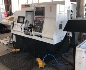
- Comparison to Alternatives (Table for Sheet Metal Context):
| Feature/Machine Type | Hydraulic Travelling Head Press | CNC Turret Punch Press | Hydraulic Guillotine Shear |
|---|---|---|---|
| Primary Use | Die-based blanking of shapes | Multi-tool punching | Straight-line shearing |
| Tonnage Range | 10-150 tons | 20-100 tons | 50-500 tons |
| Material Thickness (Steel) | Up to 2-3 mm | Up to 6 mm | Up to 20 mm |
| Precision | ±0.1 mm (with PLC) | ±0.05 mm | ±0.5 mm |
| Automation Level | Manual to full CNC | High (CNC standard) | Manual/semi-auto |
| Best for Sheet Metal | Nested blanks, prototypes | High-volume holes | Edge trimming |
| Cost (Entry-Level) | $20,000-$50,000 | $100,000+ | $10,000-$30,000 |
In summary, for the sheet metal sector, the Hydraulic Travelling Head Cutting Press Machine serves as a reliable, adaptable tool for precision blanking in thin materials, bridging manual craftsmanship and automation. Selection depends on tonnage needs, material type, and production volume—consult manufacturers for custom configurations.