What is Automatic Shearing & Piling System?

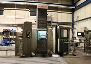
An Automatic Shearing & Piling System is an integrated, automated production line designed for high-volume processing of sheet metal in the fabrication industry. It combines automated material handling, precision cutting (shearing), and organized stacking (piling) of cut sheets to minimize manual intervention, reduce labor costs, and enhance throughput. These systems are particularly suited for the sheet metal sector, where large-format metal sheets (e.g., mild steel, stainless steel, or aluminum) need to be cut into smaller, precise sizes for further manufacturing processes like forming, welding, or assembly. By automating the workflow, the system achieves higher accuracy, repeatability, and safety compared to manual or semi-automatic shearing operations.Technically, the system operates as a modular, CNC (Computer Numerical Control)-driven assembly, often interfacing with upstream sheet storage warehouses and downstream processing equipment. It handles sheet thicknesses typically from 0.5 mm to 30 mm and widths up to 3000 mm, depending on the model, with cutting tolerances as low as ±0.1 mm. The core principle is sequential automation: feeding raw sheets, positioning them accurately, performing straight-line or angled shears, and then sorting/piling the output for efficient material flow.Key Components and Technical ExplanationThe system is engineered as a linear or U-shaped production line, with each component synchronized via PLC (Programmable Logic Controller) or CNC controls for real-time coordination. Below is a breakdown of the primary technical elements, focusing on their functionality in the sheet metal context:
- Loading and Feeding Unit:
- Purpose: Handles the initial intake of raw sheet metal from storage or pallets, ensuring damage-free transfer to the shearing station.
- Technical Details:
- Equipped with a loading table (e.g., roller or ball transfer conveyor) and a vacuum suction system (using venturi pumps or bellows grippers) to lift and separate sheets. Sheet separators (e.g., pneumatic or electromagnetic) prevent sticking in oiled or laminated stacks.
- Sensors for sheet thickness (e.g., ultrasonic or laser gauges) and alignment (e.g., photoelectric edges) detect material properties and position the sheet. An air cushion or pneumatic lift assists in floating the sheet for precise X/Y-axis alignment against backstops.
- Automation: Servo-driven or hydraulic actuators move the sheet at speeds up to 50 m/min. For example, in systems like the Amada ATF, the loading unit includes an NC (Numerical Control) de-stacker that processes sheets up to 2500 mm x 1300 mm.
- In sheet metal processing, this prevents burrs or deformations from manual handling, maintaining flatness (critical for subsequent operations).
- Positioning and Feeding Mechanism:
- Purpose: Ensures exact placement of the sheet for repeatable cuts, compensating for material variations.
- Technical Details:
- Utilizes front-feeding or rear-feeding grippers (hydraulic or pneumatic clamps with retractable arms) to grip the sheet edges without marring the surface. The feeding distance is controlled by linear encoders or ball screws for sub-millimeter accuracy.
- Servo motors drive the feed rollers or chains, allowing programmable cut lengths (e.g., from 500 mm to full sheet width). A grating or laser safety system detects obstructions and triggers emergency stops.
- In Vistmac systems, for instance, the servo-driven fixed-length feeder integrates with hydraulic clamps that retract during shear to avoid interference, enabling continuous feeding at rates of 10-20 cuts per minute.
- For sheet metal, this component optimizes blade clearance (automatically adjusted via CNC based on thickness, e.g., 0.1-0.5 mm gap for 1-5 mm steel) to minimize shear distortion like corkscrewing or bowing.
- Shearing Mechanism (Guillotine or Swing Beam Shear):
- Purpose: Performs the actual cutting of sheet metal into specified dimensions using a high-force blade action.
- Technical Details:
- Core machine is a hydraulic or electro-hydraulic guillotine shear, where a fixed lower blade and a descending upper blade (raked at 0.5-2.5 degrees) apply shear force via ram cylinders (pressures up to 300 tons for 3m-wide cuts).
- Blade design: Segmented or monolithic high-carbon steel blades with four usable edges (rotatable for longevity, up to 10,000 cuts per edge). Rake angle adjustment reduces material twist in narrow strips.
- Automation: CNC controls calculate optimal parameters (e.g., stroke length 50-150 mm, cutting angle via servo tilt). Integrated hold-downs (pneumatic fingers) secure the sheet to prevent slippage.
- In LVD HGS models, the system handles mild steel up to 30 mm thick with automatic blade gap calculation, ensuring clean, burr-free edges (shear angle minimizes fracture zone to <10% of thickness).
- For sheet metal sector: This produces straight, square cuts essential for nesting in fabrication, with minimal kerf loss (blade thickness ~0.5-1 mm) and support for thin sheets via air floats to avoid sagging.
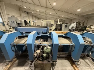
- Discharge and Piling (Stacking) Unit:
- Purpose: Collects, sorts, and stacks cut sheets or strips automatically, preparing them for storage or next-stage processing.
- Technical Details:
- Comprises conveyor belts (e.g., double-belt systems with hydraulic lifts) and a stacking table or magnetic/pneumatic pile former. The first conveyor supports the sheet during exit, while a “return to sender” mechanism (e.g., flip-over flap) redirects offcuts to the front for re-shearing.
- Piling: Automated destacker or stacker uses vacuum or magnetic lifters to layer sheets neatly, with side pushers for alignment. Height sensors (e.g., ultrasonic) trigger unloading when stacks reach 500-1000 mm.
- Scrap management: Residual strips fall through a scrap flap into bins, with conveyors for offcut recycling.
- In SafanDarley systems, the discharge includes a sheet support function for thin materials (<1 mm) and automatic transport to piling zones, achieving stack accuracies of ±2 mm.
- In sheet metal applications, this ensures organized output (e.g., sorted by size), reducing handling damage and enabling integration with robotic arms for 24/7 operation.
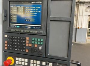
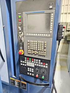
Overall Workflow and Technical AdvantagesThe workflow is orchestrated by a central HMI (Human-Machine Interface) touchscreen for programming cut patterns (e.g., via CAD import or manual input). A typical cycle: Load sheet → Sensor alignment → Feed to cut position → Clamp and shear (multiple passes for multi-cut jobs) → Discharge to conveyor → Pile/sort → Unload stack. Cycle times range from 5-15 seconds per cut, with throughputs up to 50 tons/hour.Technical Benefits in Sheet Metal Sector:
- Precision and Quality: CNC automation ensures dimensional accuracy (±0.05-0.2 mm), reducing secondary trimming and waste (material utilization >95%).
- Efficiency: Reduces operator involvement by 80-90%, with energy-efficient hydraulics (e.g., variable pump drives) and integration with Industry 4.0 for predictive maintenance via IoT sensors.
- Safety and Versatility: Interlocks, light curtains, and auto-lifts prevent accidents; adaptable for various metals (e.g., galvanized steel with anti-corrosion blades).
- Scalability: Modular design allows connection to laser cutters or press brakes, forming full sheet metal lines.