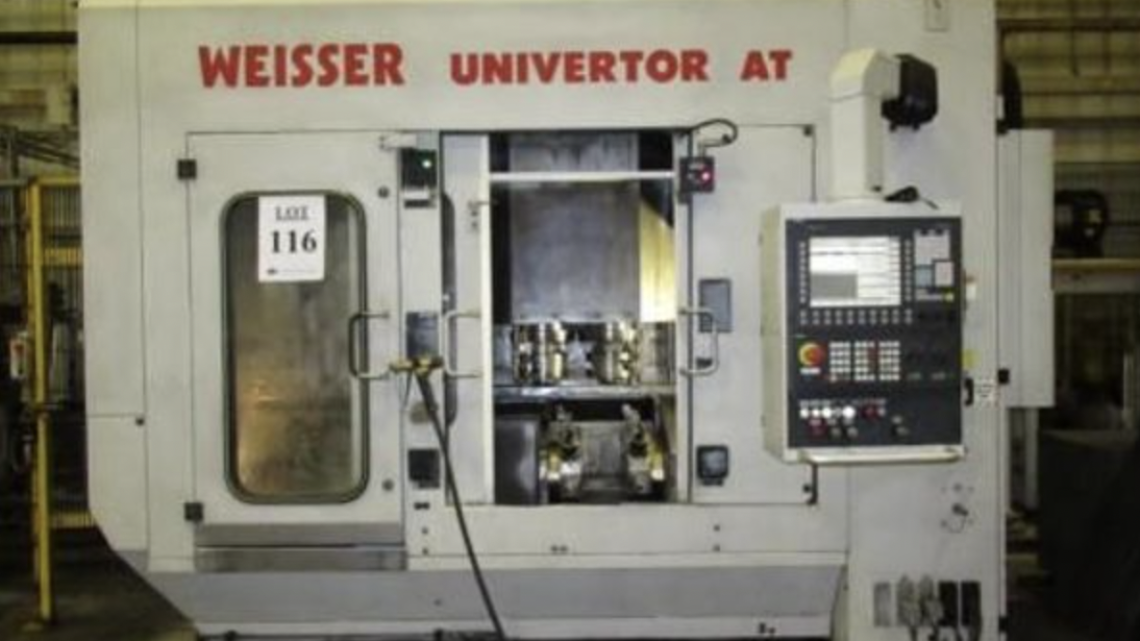
Technical Evaluation Guide: How to Identify a Quality Used, Secondhand, Pre-Owned, Surplus WEISSER UNIVERTOR AT CNC Vertical Lathe made in Germany
1. Expected Features & Spec Benchmarks
Before you inspect, try to get the original build / configuration sheet by serial number. Use it as a benchmark. Meanwhile, here are a few data points from used listings and the Weisser / Univertor family that help you know what to expect (or spot anomalies):
- A used listing for “WEISSER Univertor AT (2007)” shows X axis travel ~ 400 mm, Y axis travel ~ 200 mm and Z travel ~ 500 mm.
- That listing also mentions dual 12-station turrets and spindle speed up to 5,000 rpm.
- The Univertor / Univertor AS series machines by Weisser are described in their product literature as “modularly designed, monobloc cast base, high stiffness, precision linear guides, heavy ribbing, integrated automation, optional turrets, optional rotational turning, optional grinding / milling integrations.”
- The Univertor AS catalog states base castings with heavy ribbing, excellent damping, sturdy thermal stability, modular turret / tool options, etc.
So if your candidate Univertor AT has drastically lower travels, few tool positions, or weak structure, that’s cause for suspicion.
Key features to expect:
- Rigid cast base / heavy structure
- Precision linear guideways (or box ways) in X / Z (or whatever axes exist)
- Robust spindle design (vertical orientation or partial vertical hybrid)
- Automatic turret(s) and tool indexing mechanism
- Good protective covers, seals, bellows
- Integration of control / CNC system (likely Siemens or similar)
- Capability for turning + possible milling (if AT variant includes live tooling)
Use the spec sheet to compare what you see.
2. Documentation & History Review
Before touching the machine, demand as much documentation as possible. Many failures are due to unknown service, repairs, or abuse.
Essential documents / records to request:
- Original build / factory spec sheet / configuration drawing (with options, machine variant)
- Service / maintenance logs: spindle rebuilds, alignment checks, lubrication, repairs
- Operating hours (spindle hours, motion / axis hours, production vs idle)
- Repair / modification history: structural repairs, turret swaps, spindle replacements, part replacements
- Calibration / metrology / alignment test reports (if any)
- Tooling / fixtures / turret / spare parts included
- Control / CNC parameter archives, alarm / fault history
- Electrical / wiring diagrams, spare modules, motor nameplates
If the seller can’t provide credible records, treat the machine as higher risk and insist on more thorough on-site testing and warranty coverage.
3. Visual / Structural / Static Inspection (Machine Powered Off)
Walk the machine while it’s powered off, and inspect everything you can see. Many issues reveal themselves visually.
Structure, Base & Castings
- Look for cracks, weld repairs, distortions in the base, column, cast structure.
- Check for corrosion, pitting, rust spots, especially in corners, under covers, where coolant / chips may collect.
- Inspect mounting surfaces, leveling pads, base footings for wear or deformation.
- Ensure covers, chip shields, guards, way covers, bellows or wipers are intact. Missing or damaged covers are red flags (they allow contamination).
- Evaluate welds / seams / joints: no misalignment or gaps.
Guideways / Rails / Linear Surfaces
- Examine exposed guideway / slide surfaces (X / Z—or whichever axes exist) for scoring, scratches, pitting, wear bands.
- Check protective elements (covers, bellows, scrapers) for damage or missing parts.
- Inspect rail ends and transitions for anomalous wear.
Turret(s) & Tooling Mechanism
- Inspect turret body, pocket faces, indexing cam surfaces, gripper jaws for wear, cracks, misalignment, chipped pockets.
- Look for signs of turret wobble: loose joints, side play, worn indexing drive.
- Examine turret slide rails, bearing surfaces for scoring or wear.
Spindle & Spindle Interface
- Inspect spindle nose / taper face: pitting, dents, uneven wear, corrosion.
- Check spindle housing and bearing cover region for oil seepage, stains, signs of seal failure.
- Look for evidence of past repairs or modifications.
Electrical Wiring, Control Cabinet, Connections
- Open and inspect electrical cabinets: check wiring insulation, connector quality, absence of charred wiring, splices.
- Inspect cable carriers / conduits / wiring paths for wear, chafing, slack.
- Check motor mounts, couplings, alignment of cables / wires.
Coolant / Lubrication / Chip Handling
- Inspect coolant piping, hoses, nozzles, valves, joints for leaking, corrosion, cracks.
- Check lubrication lines / fittings to axes for integrity, leaks, or missing lines.
- Inspect chip conveyor or chip removal systems: belts, trays, screw conveyors, for wear / misalignment.
If you see structural damage, missing critical covers, heavy corrosion, or evidence of abuse, those should strongly influence your risk analysis or pricing.
4. Mechanical / Kinematic / Static Checks
If the machine allows jogging or slow manual motion in safe mode, perform tests to sense mechanical behavior: binding, backlash, play, or misalignment.
Axis Motion (X / Z or equivalents)
- Jog each axis slowly and feel for binding, grit, jumps, stiff zones.
- Reverse direction at various points and measure backlash / hysteresis with a dial indicator (command +X then –X, see lag).
- At multiple positions, mount an indicator to test straightness or deviation from ideal travel path.
Turret / Indexing
- Manually or in slow jog, index the turret across several positions. Observe hesitation, misindexing, jerkiness, or play.
- Test turret locking: once indexed, attempt to rock or move the turret slightly; minimal residual motion should be present.
Spindle / Toolholder Static Play
- Mount a clean, precision toolholder or test bar (if possible). Gently twist or tap to detect radial or axial play—should be minimal.
- Use a dial indicator to measure runout at the tool tip or taper face.
- Perform a marking / dye test on taper seating: apply thin marking layer, seat the toolholder lightly, rotate slightly, remove and inspect contact patch. The contact should be uniform.
5. Power-On / Dynamic / Functional Tests
Once power is available and safe, execute dynamic / motion / spindle tests, ideally under light load or dry run conditions.
Control / CNC Initialization & Interface
- Power up the machine and observe boot / initialization, error & fault logs, parameter loading.
- Test manual commands / jog from the control console; verify axes move as commanded.
- Run homing / reference cycles on axes, turret, ensure consistent referencing.
- Execute a motion-only (no cut) test program combining multiple axis moves (X / Z / turret) to check multi-axis behavior, smoothness, collision avoidance.
Axis Performance under Motion
- Execute box / ladder / rectangular move patterns and measure deviation (via external indicator or displacement measurement) to verify repeatability, linearity, hysteresis.
- Run return-to-zero or repeated cycles and measure drift or deviation.
- Observe acceleration / deceleration: watch for overshoot, lag, oscillation, servo instability.
Spindle Testing
- Ramp spindle from low to maximum speed. Listen / look for vibration, bearing noise, irregular acceleration.
- Monitor spindle motor current draw, stability, temperature.
Light Machining / Turning Test (if safe)
- Mount a workpiece (soft material like aluminum) and perform a light turning pass. Evaluate surface finish, consistency, tool stability, chatter.
- Compare resulting dimensions vs programmed geometry.
- During cutting, observe axis responses, vibrations, tool behavior.
Turret / Tool Change Cycles
- Execute turret indexing / tool change via CNC, watch for speed, hesitation, errors, misloads.
- After several cycles, re-check tool offset / position consistency.
Warm-Up / Thermal Behavior
- Run spindle + some motion for ~30 to 60 minutes to allow thermal stabilization.
- After warm-up, repeat reference moves, test cuts, return-to-zero to detect drift.
- Monitor motor / spindle / axis temperatures to identify hot zones.
6. Metrology / Precision & Performance Verification
With precision instruments (indicators, test bars, etc.), verify actual achievable precision of the machine.
- Linearity / straightness: over full axis travel, measure deviation from an ideal straight line.
- Orthogonality / squareness: check whether axes (X vs Z) are perpendicular within tolerance.
- Backlash / reversal error: measure hysteresis in axes via small offset + reverse.
- Tool / spindle runout: mount test bar and measure radial / axial deviation.
- Tool change repeatability: after tool changes, measure position consistency.
- Thermal repeatability: compare measurements pre- and post-warm-up.
- Turning / test cut accuracy: machine a part with known geometry, measure deviation from the programmed target.
- Surface finish / chatter / vibration evaluation: inspect machined surfaces for irregularities.
Compare your measured deviations to acceptable tolerances for your intended production work and to the original spec sheet (if available).
7. Key Red Flags & Warning Signals
As you inspect and test, watch for these warning signs. Encountering many of them is a signal to reduce your offer or walk away.
- Excessive or erratic backlash or slop in axes
- Binding, stiction, non-uniform resistance in axis motion
- Spindle bearing noise, vibration, or detectable play
- Toolholder taper damage or inability to obtain uniform contact in a dye test
- Turret indexing hesitation, misalignment, wobble or play
- Significant thermal drift shifting geometry after warm-up
- Poor repeatability returning to zero or repeated moves
- Structural repairs, welds, cracks, or deformation in critical castings
- Missing or damaged covers, bellows, seals allowing contamination ingress
- Control / CNC errors, parameter corruption, frequent alarms
- Overheated motors, drive anomalies, current spikes
- Lack of maintenance history or undocumented modifications
- Obsolete or unsupported control / electronics
If you see several of these, your negotiation leverage must be high, or you should consider rejecting the unit.
8. Refurbishment / Risk Buffer Planning
Even a well-kept used machine often needs refreshing. Factor these into your cost / offer:
- Spindle bearing replacement or overhaul
- Re-scraping / refurbishing guideways, slide surfaces
- Replacement / servicing of ball screws, nuts, encoders
- Turret / indexing mechanism overhaul
- Control / drive electronics repair or updating
- Re-lubrication, cleaning of coolant and chip systems
- Replacement of covers, seals, wipers, bellows, cable carriers
- Calibration, alignment, metrology, test cuts after installation
- Rigging, leveling, installation at your site
- Contingency for hidden internal wear (allocate 10–20 % buffer or more)
9. Contract / Acceptance Safeguards & Test Protocols
To protect your purchase, embed these terms and test requirements in your contract / purchase agreement:
- On-site / acceptance test period: require full operational testing (motion, spindle, turret, test cuts) under your environment before final acceptance.
- Acceptance criteria / tolerance schedule: define acceptable thresholds for backlash, runout, repeatability, drift, test cut accuracy.
- Sample turning / test part runs: bring your representative parts or test coupons; require the seller to produce them for measurement.
- Independent inspection clause: allow a third-party metrology / machine-tool specialist to assess machine performance before final payment.
- Warranty / guarantee clause: for critical subsystems (spindle, axes, turret) for a set period after installation.
- Holdback / retention clause: retain part of payment until acceptance criteria are verified.
- Seller disclosure clause: require disclosure of known wear, repairs, modifications, or performance limitations.