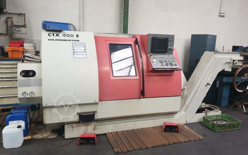
Technical Evaluation Guide: How to Identify a Quality Used, Secondhand, Pre-Owned, Surplus Gildemeister CTX400 CNC Lathe made in Germany
Reference / Benchmark Specifications (for Gildemeister CTX 400 Series)
Before going on site, obtain the original build spec sheet for the exact serial / variant. Use this to verify deviations or modifications. Meanwhile, here are typical published specs for CTX 400 series machines to guide your inspection:
| Parameter | Typical Published Value(s) | Notes / Sources |
|---|---|---|
| Swing over bed | ~ 500 mm | WMW datasheet: turning diameter over bed: 500 mm |
| Swing over cross slide / face-slide | ~ 290 mm | WMW spec: “turning dia over face slide: 290 mm” |
| X-axis travel (turret slide) | ~ 220 mm | CTX 400E datasheet: X = 220 mm |
| Z-axis travel / turning length | ~ 635 mm | CTX 400E spec: Z = 635 mm |
| Spindle maximum speed | 5,000 rpm | From CTX 400E datasheet: “Speed (max.) = 5,000 rpm” |
| Spindle power | ~ 21 kW | CTX 400E spec: “Power (max.) = 21 kW” |
| Spindle torque | ~ 240 Nm | CTX 400E spec: “Torque (max.) = 240 Nm” |
| Bar capacity / spindle bore | ~ 65 mm | CTX 400E spec: bar capacity 65 mm |
| Turret / Tooling | 12-station turret, VDI 30 tooling | CTX 400E: “Turret with 12 stations, taper VDI30” |
| Rapid traverse (X / Z) | ~ 20 / 24 m/min | CTX 400E spec: “Rapid in X 20 m/min, in Z 24 m/min” |
| Tailstock (if present) | Quill stroke ~ 100 mm, taper MT4 | CTX 400E spec: tailstock quill, stroke 100 mm, taper MT4 |
| Machine weight & dimensions | ~ 5,100 – 5,500 kg, footprint ~ 3,200 × 1,750 × 1,750 mm | Muller Machines spec: weight ~ 5,100 kg; dims ~ 3,400 ×1,940 × 1,700 mm for CTX 400 |
Use these as your “checkpoints.” If the candidate machine deviates greatly (much lower spindle power, shorter strokes, fewer tool positions), demand explanation (modified variant, stripped, etc.) and adjust risk accordingly.
1. Documentation & History Review
Before powering or touching anything, collect as much documentation as possible. A well-documented machine lowers risk substantially.
Key Documents to Request:
- Original build / as-delivered specification sheet / data sheet for that serial number (options, spindles, tool turret, control version)
- Maintenance / service logs: spindle overhauls, alignment checks, lubrication records, repairs
- Operating hours (spindle hours, axis motion hours, production vs idle)
- Repair / modification history: structural repairs (welds), turret changes, control upgrades, parts replaced
- Calibration / metrology reports: prior tests of straightness, backlash, runout, repeatability
- Tooling / accessories / spares inventory (chucks, tool holders, collets, fixtures)
- Control / CNC parameter backups, alarm history
- Electrical schematics, wiring diagrams, parts manuals
If the seller cannot provide solid and credible documentation, treat the machine as higher risk and plan for more rigorous on-site inspection.
2. Cold / Visual / Structural Inspection (Machine Powered Off)
Walk around the machine carefully and inspect all visible parts and structure. Many major issues can be spotted visually.
Frame, Bed, Castings, Structure
- Look for cracks, weld repairs, distortions in the base, bed, headstock, column, or turret supports.
- Check for corrosion, pitting, rust especially in corners, under covers, or where coolant / chips may have accumulated.
- Inspect mounting / bolted joints for any looseness, shifting, or misalignment.
- Ensure covers, guards, chip shields, way covers, bellows, guards are present and intact. Missing or damaged guards are a red flag (likely internal contamination).
Slideways, Guideways & Carriage / Turret Slides
- Inspect exposed linear guide / slide surfaces on the X and Z axes for scoring, scratching, pitting, uneven wear patterns.
- Check protective wipers, scrapers, way covers / bellows: if these are damaged or missing, internal surfaces are likely contaminated.
- Examine transition zones (start / finish of travel) where wear is heavier.
Spindle Nose / Taper / Housing
- Examine the spindle nose / taper face carefully for pitting, dents, wear, discoloration.
- Look around the spindle housing, bearing covers, and sealing surfaces for signs of oil leakage or staining.
- Check for evidence of past repairs or alignment marks.
Turret & Tooling Mechanism
- Inspect the turret body, pocket faces, cam or indexing surfaces, gripper or clamping surfaces for wear, misalignment, or damage.
- Check for turret wobble / play (looseness in turret indexing or locking mechanism).
- Examine turret slide rails, bearing surfaces, and support structure for wear, chipping or scoring.
Tailstock (if present)
- If the machine is equipped with a tailstock, inspect the tailstock quill, body, taper, and its guide for smoothness, wear or damage.
Wiring, Electrical Cabinets & Connections
- Open control / electrical cabinets — inspect wiring insulation, connectors, panel cleanliness, signs of overheating or past repair.
- Check cable carriers, motor cables, control wiring for chafing, slack, broken loops, damaged insulation.
- Inspect coolant / lubrication lines, hoses and fittings for leakage or wear.
3. Mechanical / Kinematic / Static Tests (Manual / Jog Mode)
Where safe / permissible, jog axes and test mechanical behavior, backlash, binding, and play.
Linear Axes (X / Z) Motion Tests
- Jog the X-axis and Z-axis slowly over limited segments. Feel for binding, rough spots, gritty zones, jumps.
- Reverse direction and measure backlash / hysteresis via dial indicator (command +X, then –X, see lag). The hysteresis (backlash) should be minimal and consistent.
- At various positions along travel, mount a dial indicator and measure deviation from ideal, i.e. whether motion is linear and consistent.
Spindle / Toolholder Static Checks
- Mount a clean, precision toolholder / test bar (one you trust). Gently twist or tap to feel for radial / axial play — it should be negligible.
- Use a dial indicator to measure runout at the tool tip or taper face.
- Perform a marking / dye test: coat the taper seating surface lightly, seat the toolholder, rotate slightly, remove it, and inspect the contact patch. Uniform full contact is the goal; partial patching indicates wear or misalignment.
Turret / Indexing Static Test
- Manually index the turret (if allowed) through some positions in slow / manual mode. Observe for hesitation, misindexing, binding, or play.
- Test turret clamping / locking — once indexed, check for residual movement or looseness.
4. Power-On / Dynamic / Functional Tests
When safe to power up, activate motors and test dynamic behaviors of axes, turret, spindle, and perform light machining if possible.
Control / CNC System & Interface
- Power on CNC / controller and observe initialization, error logs, axis enable state.
- Jog axes from the control console, test manual / incremental moves.
- Execute homing / reference cycles for all axes and confirm consistent referencing.
- Run a motion-only program (no cutting) combining X & Z moves to test axis coordination, smoothness, and absence of stalling or alarms.
Axis Motion Behavior
- Program “box” or ladder movements (X then Z then back) and monitor with an external indicator or displacement sensor to check repeatability, straightness, hysteresis.
- Execute return-to-zero sequences; measure any deviation.
- Observe acceleration / deceleration behavior: detect overshoot, lag, or servo oscillation.
Spindle Testing
- Ramp the spindle gradually from slow to maximum (e.g. 5,000 rpm) while observing for bearing noise, vibration, or unusual behavior.
- Monitor motor current draw, temperature, whether it holds rpm under minor load.
Light Cutting / Turning Test (if possible)
- Mount a soft material (e.g. aluminum or test alloy) and run a light turning or facing cut to test real-world performance: surface finish, chatter, stability.
- Measure the part dimensions vs programmed geometry to check cutting accuracy.
- During cutting, monitor whether axis reactions, vibrations, or anomalies appear.
Turret / Tool Change Cycle Test
- Run automated turret indexing / tool change cycles via CNC. Observe speed, accuracy, any hesitation or misloads.
- After several cycles, re-check tool tip positions (post-change) for drift.
- Verify turret locking and tool seating consistency.
Warm-Up / Thermal Drift Behavior
- Run machine (spindle + motion) for 30 to 60 minutes or more to allow thermal stabilization.
- Then repeat reference moves, test cuts, or return-to-zero routines to detect any geometry drift.
- Monitor how motors, axes or structure warms up and whether shifts in position or alignment occur.
5. Metrology / Accuracy Verification
Using precision metrology tools (indicators, test bars, laser systems if available), verify whether the machine meets acceptable precision.
- Linearity / straightness of axes (X, Z) over full travel — measure deviation from ideal straight line.
- Squareness / perpendicularity: check whether X and Z axes are orthogonal within your tolerance limits.
- Backlash / reversal error: quantify hysteresis in both axes via repeated small moves.
- Spindle / tool tip runout: measure radial and axial runout of the mounted test bar.
- Tool change repeatability: after tool changes, measure tool offsets and deviation.
- Thermal drift / repeatability: compare measurements before and after warm-up.
- Test part accuracy: machine a test geometry (e.g. step, bore, taper) and measure deviation vs program.
- Surface finish / chatter: examine machined surfaces for irregularities, waviness, chatter marks.
6. Red Flags & Warning Indicators
During your inspection and testing, be on high alert for these warning signs. Multiple or severe occurrences should force you to discount aggressively or reconsider.
- Large, irregular, or inconsistent backlash in X or Z axes
- Binding, “sticky” zones, or dead spots in axis motion
- Spindle bearing noise, vibration, or detectable play (static or at speed)
- Toolholder / taper wear, inability to seat tool uniformly (dye test failure)
- Turret indexing issues: hesitation, misindex, looseness, misalignment
- Thermal drift that causes geometry to shift significantly
- Poor repeatability on reference or return moves
- Structural repairs / welds in critical castings or frame elements
- Missing or damaged covers, bellows, seals — signs of contamination ingress
- Frequent CNC / controller errors, parameter corruption, axis disable faults
- Motors / drives overheating, abnormal noise, current anomalies
- Poor or missing maintenance history, undocumented modifications
- Obsolete control parts or unavailability of spares for turret / drives
7. Risk Buffer & Refurbishment Cost Estimation
Even with a “good” used CTX 400, you should allocate budget for refurbishment. Key items include:
- Spindle bearing replacement or overhaul
- Re-scraping / re-lapping guideways, carriage surfaces
- Replacement of ball screws, nuts, encoders/feedback devices
- Turret repair / cam surfaces, indexing carriage refurbishing
- Refresh or replacement of drive / servo electronics, wiring
- Re-calibration, alignment, metrology verification, test cuts
- Replacement of covers, wipers, seals, bellows, cable carriers
- Installation, leveling, commissioning at your site
- Contingency margin (10–20 % or more) for hidden wear or damage
8. Contract / Acceptance Safeguards & Test Protocols
To protect your investment, include the following in the purchase agreement and acceptance procedure:
- On-site / acceptance test period: require full operational testing (motion, spindle, cutting, turret cycle) on your material or test piece before final acceptance
- Acceptance criteria / tolerance schedule: specify allowable maximum deviations in backlash, runout, repeatability, geometry drift, test-cut accuracy
- Test part / sample machining: bring representative parts / test coupons so the seller must produce them for measurement
- Independent inspection clause: permit a third-party metrology / machine-tool technician to audit condition before final payment
- Warranty / guarantee clause: for key subsystems (spindle, axes, turret) over a defined period after installation
- Retention / holdback clause: withhold a portion of payment until acceptance benchmarks are satisfied
- Disclosure requirement: seller must fully disclose prior repairs, modifications, limitations, or defects