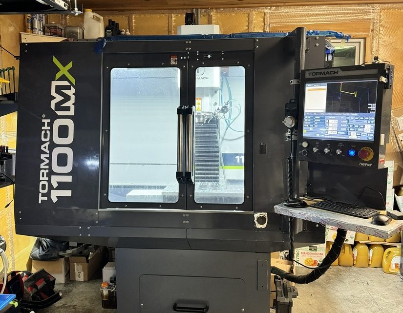
Technical Evaluation Guide: How to Identify a Quality Used, Secondhand, Pre-Owned, Surplus Tormach 1100MX CNC Vertical Machining Center made in USA
A. Key Specifications & Design Features (as Baseline)
Knowing the “as new” specs gives you reference points to detect degradation or deviations. Below are some of the published specs for the Tormach 1100MX:
| Parameter | Spec (typical / published) |
|---|---|
| X-axis travel | 18 in (457 mm) |
| Y-axis travel | 11 in (279 mm) |
| Z-axis travel | ~16.25 in (413 mm) |
| Spindle power | 2 hp (1.49 kW) |
| Maximum spindle speed | 10,000 rpm |
| Transmission | Poly-V belt drive |
| Spindle taper | BT30 |
| Maximum feed / rapid rates | ~300 IPM (X & Y) ~230 IPM (Z) |
| Resolution / accuracy | 0.0001″ resolution; ball screw positional accuracy ≤ 0.0006 in/ft; positional accuracy ≤ 0.0013 in/ft |
| Table size / load | 34 in × 9.5 in table with 3 × 5/8″ T-slots; max on table ~500 lb |
| Machine weight / footprint | ~1,600 lb (~726 kg); footprint ~69″ × 56.5″, height ~96″ |
| Frame / construction | Cast-iron frame and table; hand-scraped hydrodynamic ways; way surfaces with low friction PTFE/acetyl filled material (like Turcite / Rulon) |
Use these as benchmarks. If a used unit deviates significantly (e.g. large backlash, worn way geometry, failure to reach feed rates), it indicates excessive wear or damage.
B. Pre-Inspection & Documentation Review
Before touching the machine, gather all possible documentation and history. A well-documented machine is always less risky.
| Item | What to Request / Check | Why It Matters |
|---|---|---|
| Serial number, build date / manufacturing batch | Helps trace parts, configuration, revisions, and original factory records. | |
| Original manuals, parts list, wiring/electrical schematics, alignment / calibration sheets | Essential for repair, alignment, ordering parts, and understanding tolerances. | |
| Maintenance & servicing logs | Regular oiling, calibration, spindle bearing replacement, belt changes are good signals. | |
| Repair / crash / collision history | If the machine has been subject to collisions, crashes, or repairs, hidden misalignments or stresses may exist. | |
| Upgrades / component replacements | Perhaps the machine has had spindle upgrades, control updates, or belt changes — these could be beneficial or harmful. | |
| Spare tooling, accessories, tooling holders, fixtures | Having extra tool holders, collets, probes, etc. included is a plus. | |
| Warranty / “as is” status / return clause | See if there is any short-term return or guarantee; “sold as-is, no recourse” means more risk. |
If the seller is unwilling to provide meaningful documentation, that is a red flag.
Also talk to operators or maintenance staff: ask about typical usage (materials, hours, load cycles), recurring faults, or component replacements.
C. Visual & Structural Inspection
Once on site, with the machine powered off, thoroughly inspect all surfaces, covers, and structure.
Frame, Base & Enclosures
- Inspect the machine base, column, and frame for cracks, weld repairs, distortions, or signs of stress.
- Check leveling surfaces, mounting points, anchoring bolts, and inspect whether the machine has been re-leveled or shimmed heavily (which might indicate prior problems).
- Examine enclosures, covers, doors: missing, bent, or broken covers allow debris ingress which accelerates wear.
- Check the coolant tank, coolant lines and overflow trays: look for corrosion, leaks, or buildup of sludge.
Way Covers, Bellows, Wipers & Guards
- Check way covers, bellows, or telescopic covers: are there tears, holes, misalignments, or gaps? Damaged covers let chips and coolant invade the guideways.
- Examine wiper strips, scrapers, seals for condition (they often wear first).
- Look for signs of chip infiltration or coolant pooling near the ways or under the covers.
Table, T-Slots & Work Mounting Surface
- Inspect the table surface: is it flat, free of deep gouges, corrosion, or pitting?
- Check T-slots: look for wear on edges, deformation, burrs or damage.
- Inspect clamping fixtures, vises, and how they were mounted: damage or misuse in these areas often hints at rough usage.
Spindle Nose, Drawbar, and Tool Holder Interface
- Examine the spindle nose and drawbar area for nicks, burrs, corrosion, or flattening.
- Inspect the interface (BT30 taper) for wear lines, signs of poor seating, or damage.
- Check whether the drawbar mechanism operates cleanly (if possible) and is free from damage or binding.
Axis Leadscrews, Ball Screws & Nut Housings
- Inspect leadscrews / ball screws (if accessible) for wear, pitting, bent or corroded segments.
- Check nut housings, couplings, and end bearings for looseness, play or visible damage.
- Observe any oil or grease leakage around screw ends or bearing housings.
Linear Guides / Slideways / Gibs
- If the machine uses linear guides or box-way slides, inspect for scoring, rust, corrosion, indentations, or uneven wear.
- Check gibs (if applicable): look for wear, adjustment range, and whether they have been overtightened.
- Check lubrication channels or lines feeding the slides: are they intact, clear, or have they been blocked or bypassed?
Cable Trays, Wiring, Junction Boxes & Electrical Panels
- Open electrical enclosures (if allowed) and inspect wiring, wires, connectors, terminal blocks: look for burnt insulation, discoloration, repaired splices, or moisture ingress.
- Check for proper cable management (cable carriers, drag chains) and ensure cables are not rubbing edges or under strain.
- Inspect for corrosion, dust accumulation, and whether enclosures are sealed.
Cleanliness & Visual Signs of Use / Abuse
- Is the machine generally clean and well-maintained, or heavily caked with chips, oil, and residue?
- Look under covers and in hidden recesses for signs of neglect or hidden damage.
- Make note of any non-OEM modifications, welded patches, or inconsistent parts.
Take photos of all parts, including wear areas, wiring, and suspicious regions.
D. Mechanical & Motion Testing (Live / Powered Tests)
If possible, run the machine and evaluate dynamic behavior. Do this carefully (ideally with an experienced technician).
Axis Motions & Backlash / Play
- Jog each axis (X, Y, Z) through full travel at low, medium, and high speeds. Pay attention to smoothness, binding, jerks, slipping or stiction.
- Reverse direction and feel / measure backlash or “dead zone” — use a dial indicator or test probe if available.
- Command feed motions or rapid moves, and observe consistency in motion, absence of stutter or tracking errors.
Spindle Operation, Runout, Noise & Heat
- Run the spindle at various speeds (e.g. low, mid, high). Listen for bearing noise, grinding, whining, rumbling.
- Use a test bar or dial indicator to measure spindle runout at the nose or tool-holder end.
- Observe spindle housing temperature rise during operation: excessive heat may indicate worn bearings or insufficient lubrication.
- Check the drawbar (if engaged automatically) to ensure proper tool insertion and retention.
Tool Change / Tool Magazine (if equipped)
- If the machine has an automatic tool changer (ATC) or tool carousel, execute tool change cycles (no-load). Ensure reliable indexing, no collisions, smooth pick/place operations.
- Observe gripper action, tool retention force, and whether tools drop or tilt.
- Test magazine full, half, and empty cycles.
Homing / Reference / Limit Switches
- Command home / reference moves and check for repeatability.
- Jog to mechanical limits and confirm limit switch / soft limit function (i.e. machine stops, alarm, doesn’t crash).
- Check whether safe zones (axis limits) are correctly configured.
Feed / Acceleration / Deceleration Patterns
- Test accelerations / decelerations (in programs or jog) to detect overshoot, lag, or vibration.
- Under moderate load (a light cut or test pass), observe if feeds are maintained without dropouts or fluctuations.
Test Cutting / Material Load Run (if allowed)
- If possible, run a test cut in a representative material (e.g. aluminum or mild steel) using moderate parameters.
- Watch for chatter, deflection, sudden tool load changes, drive current spikes, or abnormal behavior.
- After the program, inspect the part: check dimensions, surface finish, flatness, concentricity or geometric features.
E. Accuracy / Calibration Checks & Measurements
To assess remaining precision and suitability, you should perform more rigorous tests:
- Backlash measurement on all axes (X, Y, Z) using a dial indicator: quantify the backlash in mm/inches.
- Ball bar / circularity test (if available): drive a circular path and measure circularity deviation.
- Laser interferometer / laser alignment (if you have access) to check straightness, squareness, pitch/roll/yaw errors.
- Surface finish / geometric tolerances: measure the test-cut part for flatness, parallelism, straightness, and finish.
- Thermal drift: run a lengthy test, let machine warm up, then re-measure a known dimension to see drift.
- Reversibility / repeatability: move to a position in positive direction, then retract and return; measure positional deviation.
- Tool length offset repeatability: remove and reinsert a tool and check whether Z-offset remains accurate.
Compare these measured values against typical tolerances you expect from a mill of this class; significant deviations may require repair or reconditioning.
F. Electronics, Control & Software
The control system, drives, encoders, and electronics are critical. Even a mechanically perfect machine is unusable if the electronics are failing.
Control Panel / HMI
- Test keys, buttons, knobs, display screens for responsiveness, clarity, and correctness.
- Check that the control boots cleanly, with no error messages or warnings.
- Load sample programs (G-code), move axes, and execute basic commands.
- Evaluate file I/O (USB, Ethernet, etc.).
Servo Drives, Motors & Encoders
- Inspect servo drives and motor housings: look for burnt components, swollen capacitors, smell of burning, or corrosion.
- Monitor amplifier / drive status lights for alarms or faults.
- Check motor temperatures during motion: overheating suggests stress or suboptimal condition.
- Verify encoder feedback loops: that measured motion matches commanded motion, no frequent re-synchronization or errors.
Feedback & Compensation Systems
- If the machine has backlash compensation, error correction or adaptive compensation features, test whether they operate correctly.
- If the machine uses linear scales or probe feedback systems, verify their function, calibration, and signals.
Safety, Interlocks & Limit Systems
- Test emergency stop (E-stop) functions, door interlocks, axis limit circuits and safety shields.
- Verify negative / positive safety wiring integrity (no bypassed safety circuits).
- Check that safety logic in the control is intact (not disabled or tampered).
Diagnostics & Logs
- Access diagnostic menus, fault logs, and event histories. Look for recurrent or major alarms or errors.
- Monitor real-time signals (axis loads, servo currents, errors) during motion to spot anomalies.
G. Red Flags, Warning Signs & Deal Breakers
During inspection, several warning signs should be taken very seriously. If a machine exhibits multiple of these, the risk may be too high.
- Structural damage: cracks, weld repairs, bent frame or column.
- Severe wear or damage on ways, slides, or guides (deep grooving, rust pitting, indentations).
- Spindle bearing noise, high vibration, overheating, or runout outside spec.
- Excessive backlash, erratic axis motion, or slipping drives.
- Binding or jerky movement in axes, slowed motion, or inconsistent feed behavior.
- ATC / tool changer failures, misalignment, slipping tools or collisions.
- Control / drive electronics that frequently fault, overheat, or show signs of repair.
- Missing or damaged protective covers, way covers, or panels.
- Corrosion, coolant / chip ingress into sensitive areas or electrical enclosures.
- Unauthorized modifications or “hack” wiring / wiring splices.
- Absence of documentation or refusal to allow motion / cutting testing.
- Poor cleanliness, heavy sludge / chip residue, neglected maintenance.
- Spare parts not available, custom components out-of-production, or obsolete electronics.
H. Practical / Commercial Considerations
Beyond technical checks, keep in mind the real-world implications of purchasing a used machine.
- Transport / rigging / installation: the 1100MX is ~1,600 lb; consider crane, leveling, foundation, anchoring.
- Commissioning & alignment: expect to perform full alignment, calibration, baseline testing after installation.
- Spare parts lead times & cost: belts, spindle bearings, drive electronics, encoders — check whether spares are available locally or only from Tormach in the U.S.
- Operator / maintenance training: ensure you or your staff can understand Tormach’s architecture, PathPilot software, maintenance regimes.
- Software / updates / licensing: verify the installed software version, whether upgrades are included, compatibility, and licensing status.
- Resale / residual value: Tormach machines have a niche market; consider whether this model retains value or can be resold.
- Warranty or acceptance testing: negotiate a trial period or acceptance testing where you can reject if test results deviate significantly.