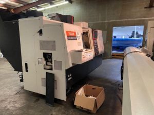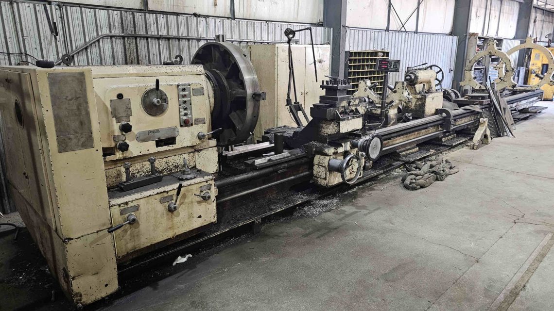
Technical Evaluation Guide: How to Identify a Quality Used, Secondhand, Pre-Owned, Surplus Poreba TR-135B1/10M Engine Lathe 10 Meters made in Poland
1. Baseline / Reference Specifications & Expectations
Before inspection, obtain as many original factory documents (drawings, spec sheets, build sheets) as possible for the specific serial number of the machine. Use them as your “benchmark” to compare what you see. Below are typical specs for a Poreba TR-135 (or close variants) from used machine listings, which you should treat as approximate guideposts (not absolute) — deviations must be explained or justified.
| Parameter | Typical / Published Value | Notes / Source |
|---|---|---|
| Swing over bed ways | ~ 53.15 inches (≈ 1,350 mm) | Poreba TR-135 listings show ~53.15″ swing over bed ways. |
| Swing over cross slide | ~ 41 in / 1,041 mm | In listings for TR-135 the swing over cross slide is given as ~ 41 in. |
| Distance between centers (i.e. bed length) | 10 m (for the “/10M” version) | In the listing for TR135-B2/10M, 396″ (~10,058 mm) is quoted. |
| Spindle bore / through hole | ~ 4.72 in (~ 120 mm) | The TR135-B2/10M listing states spindle hole diameter: 4.72″. |
| Spindle nose / taper | A1-15 (common) | The listing shows “Spindle Nose: A1-15.” |
| Spindle speed range | 5 – 500 rpm | TR135-B2/10M specs list 5–500 rpm. |
| Main motor / power | ~ 55 HP | The same listing shows Main Motor: 55 HP. |
| Max weight between centers / with steadies | Very large (tens of thousands of lbs) | The listing gives “Maximum Weight Between Centers Unsupported … 20,000 lbs” etc. |
| Bed width / cross-section | ~ 26 in (≈ 660 mm) | In TR135-B2 specs, bed width is 26″ per the MachineryValues listing. |
Use these as reference targets: if the unit you’re inspecting differs significantly (e.g. much lower swing, smaller spindle bore, weaker motor, reduced bed width) that must be scrutinized or explained (maybe it’s a variant, or parts removed).
Also note: Being a very large lathe (10 m length), rigidity, straightness over long spans, backlash, and support (steadies) become critical factors. The risk of twist, sag, thermal drift, and alignment errors grows with length.
2. Document & History Review
Begin by collecting and reviewing documents. A good history is your first defense against hidden defects.
- Original factory build sheet / as-built drawing — confirms the delivered configuration: bed length, cross-section, leadscrew arrangement, drives, tailstock, steadies, etc.
- Maintenance / service logs — ideally with dates and descriptions: oil changes, bearing replacements, adjustments, alignment checks, grinder sessions, etc.
- Operating / usage hours — especially hours under cutting (loaded) conditions versus idle.
- Repair / rebuild / modification history — any accidents, crash repairs, structural welding, bed straightening, changes to motors or drives.
- Alignment / metrology reports — if available: past straightness checks, bed alignment, centerline alignment, repeatability tests.
- Parts / consumables record — whether OEM parts used, or worn parts replaced.
- Accessories / tooling included — chucks, cyclical steady rests, follow rests, taper attachments, etc.
- Electrical / control schematics, motor name plates, wiring diagrams — ensure you have correct wiring and drive information.
If documentation is spotty or missing, factor in higher risk — plan to heavily test the machine before acceptance.
3. Visual / Structural / Cold Inspection (Machine Off)
Do a careful visual inspection before moving parts or running power. Many structural or wear issues show visibly first.
Bed, Base & Structure
- Inspect the bed ways (flat, V-guide, or combination) for cracks, weld repairs, rust, pitting, scoring, or gouges.
- Look along the bed span (especially over 10 m length): check for sag, twist, misalignment of top surfaces.
- Check for structural deformation or warpage in cross supports, frames, stead support structures.
- Look for corrosion, especially near coolant lines, chip trays, base, underside, and around fasteners.
- Inspect structural joints, welds, reinforcing ribs. Any signs of previous straightening or repair are red flags.
Headstock / Spindle Area
- Inspect the headstock casting and spindle housing: check for cracks, welds, repairs, damage.
- Examine the spindle nose / taper surface carefully: pitting, rust, gouges, discoloration, wear, or damage.
- Inspect bearing housing covers, mounting surfaces, cooling or lubrication piping.
Steadies / Support Rests
- If steady rests or follow rests are present, check their cleanliness, wear, alignment, ease of adjustment.
- Check for bearing play, surface wear, lubrication condition.
Carriage / Cross Slide / Tool Post
- Inspect cross slide, compound slide and tool post for wear, play, scoring, misalignment.
- Check dovetail surfaces (if applicable) for clearance, wear, and smoothness.
- Inspect ways under the carriage: under the cross-slide, any exposed surfaces.
Tailstock & Quill
- Inspect tailstock casting, sliding base, quill condition: check for wear, scoring, corrosion.
- Extend quill (if possible) and inspect bore, taper (if applicable), quill alignment.
Lead Screws / Feed Mechanisms / Gearing
- Inspect feed screws, lead screws, gearboxes (if exposed) for wear, backlash, damage.
- Check couplings, gear teeth, keyways, shaft interfaces.
Fasteners, Access Panels, Wiring (Cold)
- Check structural bolts: none missing, no overt signs of force / bending, torque irregularities.
- Open electrical panels and inspect wiring: look for aging insulation, splices, burns, corrosion.
- Inspect cable channels, conduit, junction boxes: no exposed wiring, no cut insulation or damage.
Fluids, Coolant Lines, Lubrication
- Examine lubrication lines or automatic lubrication systems: check whether they are intact, not clogged, no leaks or blockages.
- Inspect coolant piping, nozzles, hoses, tank areas for leaks, residue, corrosion.
If severe structural damage or missing critical parts is evident, remove the machine from serious consideration unless repair is accounted for.
4. Mechanical / Kinematic / Static Checks (Manual or Slow Jog)
With the machine safe to move (or under slow low-power jogging), conduct mechanical and kinematic tests to assess wear, backlash, stiffness.
Bed / Carriage Travel
- Move the carriage (in the longitudinal direction) slowly along the bed: feel for binding, stick-slip, jumps, rough patches, or inconsistent resistance.
- At several points along the bed, reverse direction and measure backlash / lost motion with a dial indicator (move ± small offset and back). The lost motion should be minimal and consistent.
- Use a straightedge or test indicator to check whether the carriage runs straight and true relative to the bed.
Cross Slide / Compound / Tool Post
- Move cross slide and compound slide manually (or in slow mode). Feel for smoothness, any binding, irregular motion, discontinuities.
- Reverse direction and test for backlash in cross slides.
- Check tool post / turret fit, clamping, and repeatability.
Lead / Feed Screws and Feed Mechanisms
- Jog feed screws or engage feeds slowly: monitor whether feed is smooth, whether backlash or play appears.
- If possible, reverse feed direction and measure lag.
Steady Rests (Static Check)
- If steady rests are adjustable, move them manually and test adjustment smoothness, responsiveness, constraint of workpiece, and locking mechanisms.
Carriage / Bed Clearances & Gaps
- Check alignment between carriage and bed: inspect for gaps, misfit, rocking or tilting under small manual load.
If axes bind, show high backlash, or you detect loose parts in static testing, deeper remediation is needed.
5. Power-On / Dynamic / Functional Tests
Once confident in mechanical integrity and safety, power the machine and run dynamic tests. These tests reveal issues under load, motion, and control.
Electrical / Motor / Control Tests
- Power on machine (using lowest safe settings): check for warning lights, residual alarms, control readiness.
- Test operator controls: jog, manual movement, feed engage, emergency stop response.
- Start spindle rotation (unloaded): ramp through speeds (from low to max, e.g. up to 500 rpm) and monitor for smooth acceleration, vibration, noise, heat.
- Monitor motor current draw, motor temperature, bearing sounds.
Carriage / Feed Motion Under Power
- Run carriage in longitudinal direction under powered motion: monitor for smoothness, no hesitation, stable traverse.
- Test cross feed / cross slide under power movement: monitor behavior, ability to engage and disengage feeds, smooth reversal.
- Check rapid traverse (if available) behavior, acceleration / deceleration, smoothness.
Tooling & Cutting Test (If Possible, Under Light Load)
- If safe, mount a test workpiece (metal cylinder or bar) and perform a light cut (boring, facing, turning) across the bed length. Monitor for:
- Surface finish (no chatter, no gouging)
- Dimensional accuracy vs commanded values
- Stability during cut (no drift, no vibration)
- Spindle holding torque and load consistency
Repeatability & Return-to-Zero Tests
- Command the carriage to move to multiple positions and return to zero; measure deviation.
- Execute multiple incremental moves (forward/back) and measure whether the same starting position is achieved within tolerance.
- Check whether the tool returns to same reference point repeatably.
Thermal / Warm-Up Test
- Let the spindle and machine run for a period (e.g. 30–60 min or more) under idle or light load.
- After warm-up, re-check key reference moves (e.g. carriage zero, runout, repeatability) to see how much drift occurs due to thermal expansion.
- Monitor motor temperature, bearing zones, control cabinet temperature.
6. Metrology / Alignment / Accuracy Verification
To truly confirm quality, you need precision measurement. Use dial indicators, test bars, straightedges, surface plates, or better equipment if available.
- Straightness & alignment of carriage travel over full bed length: measure deviation vs reference.
- Parallelism: between bed ways, between carriage and bed, between cross slide and carriage surface.
- Runout / spindle alignment: mount a precision test bar, measure runout, both axial and radial.
- Repeatability / backlash: measure reversal error and lag in axes.
- Sag / deflection under load: apply known load at carriage, measure vertical deflection or sag.
- Thermal drift: compare measurements before and after warm-up.
- Tool post repeatability: after tool changes or repositioning, measure whether the tool returns to same zero reference.
Compare measured tolerances vs what the factory spec allows (if known). Accept small deviations, but be cautious with large or erratic ones.
7. Red Flags & Warning Signs
Here are specific conditions that should signal caution, further inspection, or negotiation:
- Deep scoring, pitting, gouges, or corrosion on bed ways or carriage surfaces.
- Large, inconsistent, or uncorrectable backlash in longitudinal or cross axes.
- Spindle play, vibration, bearing noise, or inability to maintain precision.
- Uneven taper contact or damaged spindle nose surfaces.
- Carriage binding, sticky movement, rough patches in carriage traverse.
- Replacement or repair welds in structural areas (bed, saddle, supports) without clear documentation.
- Structural misalignment: twist, sag, non-flatness over long bed length.
- Missing or damaged covers, guards, lubrication systems, fluid lines.
- Weak or failing motors / power systems (overheating, current anomalies).
- Poor surface finish during test cutting, chatter, vibration, variation across length.
- Control instability, alarms, parameter corruption, sudden errors under motion.
- High thermal drift: geometry shifting significantly after warm-up.
- Steady rests or supports poorly adjusted, worn, or damaged.
- Lack of credible maintenance or calibration history.
- Obsolete or hard-to-replace parts (bearings, motor spares, drive components).
If you see multiple red flags, seriously question the machine’s value unless major refurbishment is planned.
8. Estimating Refurbishment / Risk Buffer
Even a well-maintained machine will often require some level of overhaul—especially at large scale. Estimate costs / risks for:
- Bed / carriage regrinding or resurfacing (to restore geometry).
- Replacement or refurbishment of carriage slide surfaces.
- Spindle bearing replacement, repair of spindle nose, taper surfaces.
- Replacement of feedscrews, leadscrews, nuts, couplings.
- Gearbox or drive train overhaul.
- Motor / electrical system refurbishes or replacement.
- Re-lapping, alignment, metrology calibration.
- Steady rest refurbishment or replacement.
- Repainting, cover repairs, lubrication system repair.
- Installation, leveling, alignment in your facility.
- Contingency (e.g. 10–20 % or more) for hidden problems.
9. Contract / Acceptance Safeguards & Test Protocols
To protect your purchase, embed the following in your contract or agreement:
- On-site test period / “burn-in”: allow the machine to be operated under light to moderate production in your facility for a defined time before final acceptance.
- Acceptance criteria / tolerance specification: define acceptable limits for backlash, runout, repeatability, straightness, drift, etc.
- Test piece / sample part run: bring a reference workpiece or test bar and have the seller machine a part you measure.
- Independent inspection clause: allow you to bring in a machine-tool / metrology specialist to audit before final payment.
- Warranty / guarantee (for critical components) for a defined period (e.g. spindle, bearings, feed drives).
- Retention / hold-back: hold a portion of payment until acceptance is confirmed.
- Disclosure requirement: seller must declare known repairs, modifications, wear, or defects.