Technical Evaluation Guide: How to Identify a Quality Used, Secondhand, Pre-Owned, Surplus Optimum Optimill F150 HSC CNC Vertical Machining Center made in Germany
1. Baseline / Reference Specifications & Expectations
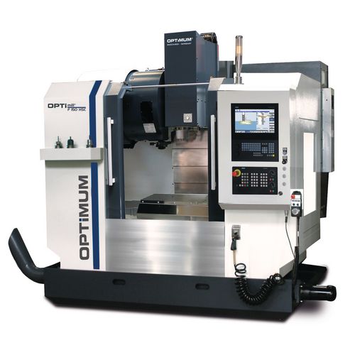
Before visiting the machine, collect the factory spec sheet or catalogue for that specific unit (serial number, HSC vs standard). Use that as your “golden baseline.” Below are typical published specs and features for the Optimum / OPTImill F-150 / F150 HSC machines to serve as reference landmarks:
| Parameter | Typical / Published Value | Notes / Source |
|---|---|---|
| Model designation | OPTImill F 150 / F 150 HSC | From OPTIMUM catalogues. |
| Spindle speed (max) | 10,000 rpm (standard), possibly up to 12,000 rpm for HSC version | For F150E standard: “Max. Spindle speed 10,000 min⁻¹” |
| Travel / axis strokes (X / Y / Z) | Example: 760 / 440 / 460 mm (for HSC configuration) | From a used F150 HSC listing: “X-axis automatic 760 mm, Y-axis automatic 440 mm, Z-axis automatic 460 mm” |
| Table size & load | ~ 900 × 410 mm table, max ~ 350 kg | Listing data: table surface 900 × 410 mm, load 350 kg |
| Rapid traverse speeds | ~ 30,000 mm/min (30 m/min) | From used listing: “Rapid traverse (X / Y / Z) 30 m/min” |
| Positioning / repeat accuracy | ± 0.005 mm (or in that order) | Used machine listing: “positioning accuracy ± 0.005 mm / repeat accuracy ± 0.005 mm” |
| Spindle motor power / torque | e.g. 21.2 kW (30% duty), 9 kW continuous | Used listing shows main spindle: 21.2 / 9 kW |
| Tool changer / tool positions | 24 tool positions (double-arm style) | From F150 HSC listing: “number of tool positions 24 pos.” |
| Weight & dimensions | ~ 4,350 kg; dimensions ~ 3,000 × 1,950 × 2,310 mm (for one listing) | From Werktuigen machine listing: weight 4,350 kg; dims ~3,000 × 1,950 × 2,310 mm |
| T-slots & tooling interface | T-slot size e.g. 16 mm (4 slots), spindle taper SK40 (DIN 69871) | From listing: T-slot size 16 mm, 4 slots; spindle holder SK40 |
Use these numbers as “checkpoints.” If the machine you inspect deviates significantly (much lower speeds, fewer tool stations, reduced travels, weak motor ratings, etc.), get solid explanations or documentation showing that it is a variant or a modified version.
Also note that HSC variants often demand better balance, spindle cooling, stiffer structure, more rigid bearings, better damping etc. So components that may be acceptable on standard machines may be borderline on HSC ones.
2. Documentation & History Review
Before or at the beginning of your inspection, gather all relevant documentation. This is crucial to reduce risk.
- Original factory / build sheet / configuration drawing for that specific machine: which options (HSC spindle, coolant, chip removal, tool changer, covers) were installed.
- Maintenance logs / service records: dates, hours, spindle rebuilds, alignment checks, lubrication system servicing.
- Operating hours / usage profile: total hours, hours of cutting vs idle / rapid motion.
- Repair / upgrade / modification history: any structural repairs (welding, straightening), replaced spindle, servo drives swapped, control upgrades, etc.
- Metrology / calibration reports: straightness / flatness checks, axis calibration, test cut records, ballbar or laser alignment results (if available).
- Spare parts & tooling inventory: which spare spindles, tool holders, covers, parts come with it.
- Control & CNC backup / parameter file archive: copies of parameters, backups, alarm logs.
- Electrical / wiring diagrams / schematics, motor nameplates, guarantee / warranty documentation (if any).
If the seller cannot provide solid documentation or only vague statements, you must rely more heavily on thorough inspection tests and demand strong warranties or price discounts.
3. Visual / Structural Inspection (Cold / Power-Off)
Carefully inspect the machine’s structure, covers, and accessible components before moving anything.
Machine Frame & Base
- Check for cracks, weld repairs, distortions, misaligned joints in base, column, knee or body castings.
- Inspect for surface corrosion, pitting, oxidation, especially in hidden areas, under covers, or beneath coolant/fluids.
- Examine whether covers, doors, way guards, bellows, chip shields, splash protection are present and intact. Missing covers often imply internal contamination.
- Look for asymmetric wear or sagging in frame joints or mounting points.
Linear Guideways & Slide Surfaces
- Examine exposed guideway (X, Y, Z) surfaces or edges for scoring, scratches, pitting, rust, uneven wear.
- Check that protective wipers, bellows, cover strips are intact and effective.
- Inspect lubrication lines or oil troughs around guideways — do they appear clean, uniform, or clogged / dried?
Spindle Housing & Spindle Nose
- Inspect spindle nose / taper interface area for pitting, corrosion, dents, discoloration, wear.
- Check housing covers, seals, glove rings, cooling lines for damage or leaks.
- Look for signs of overheating (heat discoloration) or past repair marks.
Tool Changer / Magazine
- Visually inspect tool changer arms, grippers, indexing mechanism, magazine rails for damage, wear, broken parts.
- Check for play / looseness, misalignment in arm joints, sensors, limit switches.
Fasteners, Access Panels & Wiring
- Ensure structural bolts are present, properly torqued, not visibly deformed or overworked.
- Open access panels, check for rough edges, mismatched fasteners, signs of tampering.
- Visually inspect wiring, cable carriers, conduit paths: look for frayed insulation, splices, overheating discoloration, loose wires.
Coolant, Lubrication, Fluid Systems (External)
- Check coolant piping, hoses, fittings, nozzles for leaks, corrosion, damage.
- Inspect lubrication system lines (for axis lubrication, central oil systems): are they clean, intact, no leaks.
- Look at chip conveyors, trays, sumps: any accumulation, corrosion, damage.
If you observe major structural damage or missing critical protection, that is a strong red flag (though not necessarily a deal-breaker if repairable and accounted for).
4. Mechanical / Kinematic / Static Checks (Manual or Slow Mode)
With the machine powered off (or in a safe manual mode), perform mechanical and kinematic checks to sense wear, binding, backlash, smoothness.
Axis Motion (X, Y, Z)
- Jog or carefully move (manually or in “jog / single-step” mode) each axis through its travel. Feel for binding, gritty zones, jumps, stiffness, dead spots.
- Reverse direction at various positions and measure backlash / lost motion using a dial indicator. The amount of hysteresis should be small and consistent.
- At several points along each axis, use test indicators or precision straightedges to verify straightness / pitch error (i.e. check whether movement is smooth and follows linear paths).
Ball Screws / Nuts & Guides
- If accessible, inspect ball screws: look for wear marks, scoring, corrosion. Check that nuts are not loose or exhibiting play.
- Check bearing housings at the ends of ballscrews for tightness / pre-load.
Spindle / Taper / Toolholder Play (Static)
- Mount a precision toolholder or test bar (clean, well-seated). Gently twist or tap and detect axial or radial play (should be minimal).
- Use a dial indicator to measure runout at the tool tip or taper surface.
- Perform a dye / marking compound test: apply a thin coat to taper seating surfaces, seat the toolholder lightly, rotate slightly, then remove and inspect contact patch. Uniform full-surface contact is desirable; partial or uneven contact indicates wear or misalignment.
Tool Changer / Tool Load / Magazine Checks
- Manually (or in slow mode) index the tool changer through the magazine. Observe whether indexing is smooth, without hesitation, misalignment, or binding.
- Check tool loading and unloading action: gripper arm alignment, sensor response, limit switches.
Drive / Couplings / Gearboxes (Static Checks)
- If possible, turn drives (gears, couplings) by hand (gearbox input / intermediate shafts) to sense binding, roughness, play.
- Listen/feel for stiffness, kicks, dead zones, or looseness.
Lubrication / Coolant Static Checks
- If possible, run the coolant pump(s) briefly (no machining) to check for leaks, proper flow, pump noise.
- Inspect lubrication lines for blockages or visibly dry zones.
- Check filters, sumps, and look for contamination (chips, sludge, metal particles).
If you detect severe backlash, binding, mechanical play, or visible damage in these static tests, raise the risk significantly or demand repair / discount.
5. Power-On / Dynamic / Functional Testing
With safety and permission, power up the machine and perform dynamic tests under motion and (if feasible) light cuts.
Control & CNC System
- Power on control; note boot sequences, alarm / fault logs, parameter initialization issues.
- Test the operator interface: jog, manual moves, MDI commands, incremental motions.
- Execute homing / reference cycles on X, Y, Z axes and verify repeatability and reliable referencing.
- Run a simple motion-only program (no load) combining moves in X, Y, Z, and verify smooth transitions, no stalls, no alarms.
- Test limit switches, safety interlocks, door sensors, emergency stop functionality.
Axis Performance Under Power
- Run “box moves” or patterns (X then Y then Z) while using an external indicator or measuring device to verify accuracy and repeatability.
- Test return-to-zero accuracy: move to a coordinate and return; check deviation.
- Validate acceleration/deceleration behavior: watch for overshoot, servo hunting, vibration, instability.
Spindle / Cutting / Load Test
- Ramp the spindle gradually (low → high), listening for abnormal noises, vibration, bearing hum, resonance.
- Monitor spindle temperature changes over time.
- If possible, mount a light test piece and do a light machining pass (e.g. face / contour on soft alloy). Observe surface finish, chatter, surge in motor current, stability.
- Check how the spindle holds rpm under load, and whether torque dips or vibration appear.
Tool Change / Cycle Test
- Run full automatic tool change sequences: index magazine, gripper arm move, tool swap, confirm correct tool, no collision or misalignment.
- After multiple tool change cycles, measure tool offset stability (i.e. whether tool length / position remains consistent).
- Observe speed, smoothness, synchronization between tool change and spindle readiness.
Warm-Up / Thermal Drift Test
- Let the machine run (spindle on, axes idle or moving) for a period (30–60 min or more). Then re-check reference moves (e.g. a “home-to-point” displacement) to see how much drift has occurred.
- Monitor motor / drive / axis temperature changes and see if there is thermal expansion / distortion affecting geometry.
6. Metrology / Alignment & Accuracy Verification
To ascertain actual usable precision, perform metrology checks using precision tools (dial indicators, straight edges, laser interferometers if available, etc.).
- Straightness / linearity: over each axis travel, measure deviation from linear path, pitch / yaw error, nonlinearity.
- Squareness / perpendicularity: between axes (X–Y, X–Z, Y–Z) to check orthogonality.
- Repeatability / backlash quantification: measure reversal error, backlash in axes.
- Spindle runout / taper alignment: measure tool tip runout, taper coaxial alignment.
- Deflection / stiffness: under small applied load (if safe), measure how much the spindle / column / structure flexes at extended reach.
- Thermal repeatability: measure before and after warm-up to see how geometry changes.
- Tool change repeatability: measure tool tip location before and after tool changes to see drift.
Compare these measurements with the machine’s published tolerances (if known) and what your production tolerance demands are. Minor deviations are inevitable; large or erratic deviations are serious red flags.
7. Red Flags & Warning Signs
Throughout your inspection, be alert for these warning signs. Any one of these should prompt deeper scrutiny or rejection unless adequately compensated.
- Excessive backlash / slop in any axis (X, Y, Z) that cannot be compensated or minimized.
- Deep scoring, pitting, corrosion, or damage on guideways or slide surfaces.
- Spindle bearing noise, vibration, or play during static or dynamic testing.
- Uneven or partial taper contact (bad dye test) on toolholders.
- Tool change misindexing, hesitation, collision, or tool drop.
- Control / CNC errors, parameter corruption, axis disable alarms, intermittent faults.
- High thermal drift in geometry after warm-up.
- Missing or damaged covers, bellows, way wipers, leading to contamination ingress.
- Structural repairs or welds in critical areas (column, box casting, spindle housing) with inconsistent finish.
- Non-OEM modifications or undocumented retrofits.
- Lack of credible maintenance / calibration history.
- Oversized or worn components nearing end-of-life (e.g. in the drive train).
- Hard-to-source or obsolete control / electrical / electronics spares.
If you see multiple such red flags, the machine’s risk increases significantly.
8. Cost Estimation & Risk Buffer
Even a well-maintained used machine often requires refresh or repair. Before finalizing a bid, allocate budget for:
- Spindle bearing replacement or spindle overhaul.
- Re-scraping or refurbishing guideways, slide surfaces, or regrinding.
- Replacement or overhaul of ball screws, nuts, lead screws.
- Repair or replacement of tool changer / magazine / gripper elements.
- Control / servo / drive components overhaul or replacement.
- Re-lubrication, fluid system refurbishing, coolant system cleaning.
- Re-alignment, metrology, calibration and test cut verification after installation.
- Transport, installation, leveling in your facility.
- Contingency buffer (10-20 % or more) for hidden issues.
9. Contract / Acceptance Safeguards & Test Protocols
To safeguard your investment, include in your purchase contract or agreement these terms:
- On-site test / “burn-in” period: Allow operation under load (or test cuts) for a defined number of hours in your facility before final acceptance.
- Acceptance criteria / tolerance schedule: Specify allowable tolerances (backlash, runout, repeatability, thermal drift, test cut tolerances).
- Sample parts / test cuts: Bring representative workpieces / materials and request the seller to run test cuts which you can measure.
- Independent inspection clause: Allow you to engage a third-party metrology / machine-tool specialist to confirm condition and accuracy before final payment.
- Warranty / guarantee (for critical parts): e.g. spindle, axes, tool changer, for a limited period after installation.
- Holdback / retainage: Retain part of payment until acceptance is achieved.
- Disclosure clause: Seller must declare known defects, repairs, modifications, or performance limitations.