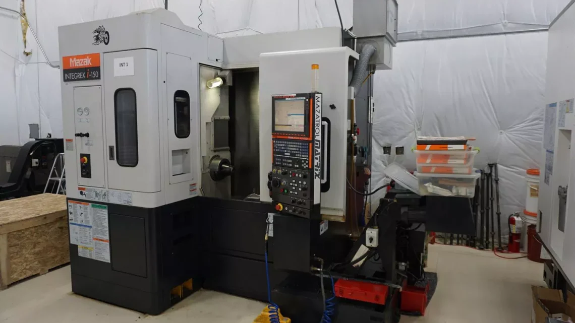
Technical Evaluation Guide: How to Identify a Quality Used, Secondhand, Pre-Owned, Surplus MAZAK INTEGREX i-150 CNC Multi-Tasking Turn-Mill Center Machine made in Japan
1. Baseline / Reference Specifications & “Golden Values”
Before you go on site, obtain (or demand) the factory build sheet or Mazak’s spec sheet for that exact machine (serial number / options). Use it as your benchmark. Meanwhile, here are published typical specs for the INTEGREX i-150 to guide your inspection and flag gross deviations:
| Parameter | Typical / Published Value | Notes / Source |
|---|---|---|
| Bar work capacity (main spindle) | Φ 65 mm (2.56 in) | Mazak Europe & US marketing data |
| X-axis travel | 370 mm (≈ 14.57 in) | Mazak Europe spec sheet |
| Y-axis travel | 200 mm (≈ 7.87 in) | Mazak spec, etc. |
| Z-axis travel | 435 mm (≈ 17.13 in) | As above |
| W-axis (sub / supplementary Z) travel | 300 mm | Mazak spec listing |
| B-axis range | –10° to +190° (i.e. 200° of tilt) | Mazak marketing spec |
| Main spindle max speed | 5,000 rpm | Mazak spec sheet |
| Main spindle motor power | 11.0 kW (40% duty) | Mazak spec for standard version |
| Milling spindle / live tool spindle speed | 12,000 rpm | Mazak’s published listing |
| Milling spindle motor | ~ 7.5 kW (20% ED) | Mazak spec sheet |
| Max swing / turning diameter | ~ 400 mm (≈ 15.75-16.8 in) | Listing data and Mazak’s marketing data |
| Max machining length (turning) | ~ 385 mm (≈ 15.16 in) | Mazak spec sheets |
| Tool magazine / tool positions | Typically 36 tools | In used spec sheets for i-150 machines |
| B-axis indexing resolution & backlash | High-accuracy roller cam drive with no backlash; indexing in 0.0001° steps | Claimed by Mazak marketing materials |
If the machine you inspect diverges significantly (e.g. much lower spindle speed, far smaller travels, fewer tool positions, weak motor power), that must be explained (option removal, nonstandard variant, or misrepresentation).
Also note: INTEGREX machines include Mazak’s Intelligent Thermal Shield for thermal compensation in some i-series models.
2. Documentation & History Review
Before or during the factory walk, collect all possible documentation. A well-documented machine reduces many risks. Key items include:
- Factory build / as-delivered specification sheet — shows which options, spindle types, live tooling, axes, etc.
- Service / maintenance logs — history of preventive maintenance, spindle rebuilds, axis alignments, lubrication intervals, repairs.
- Operating / runtime hours — total hours, and ideally distinction between “cutting load hours” vs idle/traverse.
- Repair / modification / upgrade history — any crash repairs, component replacements (spindle, B-axis, drives), retrofits, control upgrades, parts swapped.
- Metrology / calibration / alignment reports — previous straightness checks, axis calibration, backlash tests, B-axis / rotary calibration, thermal drift studies.
- Tooling / accessories / spare parts list — included tooling (fixtures, holders, tailstock, collets, etc.), spare spindles, drives.
- Electrical schematics / wiring diagrams / control backups / parameter archive — ability to restore parameter set, alarm history, whether control has been reprogrammed.
- Parts / consumables usage records — whether OEM parts used or aftermarket replacements.
If the seller is unwilling to provide credible historical records, plan to offset risk (price discount, stricter acceptance tests).
3. Visual / Structural / “Cold” Inspection (Machine Unpowered)
Conduct a thorough visual inspection of the machine’s structure and visible components before powering it. Many issues manifest outwardly first.
Machine Base, Frame & Column
- Inspect for cracks, weld repairs, deformations, misalignments in base, column, cross-structure, mount points.
- Look for corrosion, pitting, surface rust, especially in hidden areas, interior corners, underside.
- Check that covers, guards, bellows, way wipers are present and in good condition. Missing or damaged protections allow contamination of internal parts.
- Verify structural joints are tight, no looseness, no seam gaps.
Linear Guides & Slide Surfaces
- Examine the exposed linear guide surfaces (X/Y/Z axes) for scoring, scratching, pitting, uneven wear, rust.
- Confirm that protective wiper strips or bellows are intact and functional.
- Inspect lubrication troughs or rail lubrication ports — ensure lines are present and clean.
Rotary / B-axis & C-axis Structure
- Inspect the B-axis tilt table or rotational interface for signs of wear, misalignment, corrosion, backlash in visible components.
- Visual check of drive mechanisms (cams, gearing, belts, couplings) for wear, looseness, damage, missing covers.
- Inspect housing covers, seals, access flanges for tightness and no signs of leakage or repair.
Spindle Housing & Spindle Nose
- Examine the spindle nose / taper area for pitting, discoloration, corrosion, dents or gouges.
- Inspect the spindle housing, covers, cooling lines, seals, access panels — look for cracks, leaks, or damage.
- Examine the interface area where live tooling or milling heads attach — look for damage.
Tool Changer & Magazine
- Inspect the tool changer carousel, rail, turret arm, gripper mechanisms. Look for wear, misalignment, play, broken parts.
- Check index mechanisms, sensors, limit switches, guide rails.
Fasteners, Access Panels & Wiring
- Check structural bolts and mounting hardware: none missing, no signs of overtightening or distortion.
- Open access panels, inspect wiring harnesses, junction boxes: no frayed wires, no splice hacks, no overheating discoloration.
- Inspect cable tracks, conduits, wiring routes: check for chafing, slack, exposed insulation.
Coolant / Lubrication / Fluid External Systems
- Inspect coolant piping, hoses, nozzles, fittings, filters for leaks, residue, corrosion.
- Inspect lubrication lines (axis lube, central lubrication) for blockages, leaks.
- Check chip conveyors, sumps, chip trays for condition, residue, evidence of long-term neglect.
If major structural damage, missing critical parts, or visual signs of abuse are evident, proceed with caution and prepare discount negotiation.
4. Mechanical / Kinematic / Static Checks (Manual or Jog Mode)
Assuming it is safe to jog or move parts (in manual or low-speed mode), perform the following mechanical and kinematic tests to sense wear, binding, misalignment, or looseness.
Axis Movement & Backlash
- Jog each linear axis (X, Y, Z) slowly through segments of travel. Feel for binding, irregular resistance, gritty motion, “dead spots”.
- Reverse direction at multiple points and measure backlash / reversal lag using a dial indicator (small ± command and check return). The backlash should be minimal, consistent, and within the spec range (if provided).
- At selected positions, use a test indicator or gauge to check straightness / pitch deviation (i.e., measured path vs ideal straight line).
Ball Screws, Nuts & Bearings
- If accessible, inspect ball screws: look for wear marks, pitting, corrosion on threads.
- Test ball nut housings (if removable) for looseness or play.
- Check end bearings / pillow blocks for slop or looseness in their mounts.
Spindle / Toolholder Static Checks
- Mount a high-quality precision toolholder or test bar (clean, well-seated). Gently tap or twist and detect any radial or axial play. There should be minimal to none.
- Use a dial indicator to measure runout at the tool tip or taper face.
- Perform a dye / marking compound test: apply a thin uniform layer of machinist’s dye on the taper face, seat the toolholder lightly, rotate/tilt slightly, and remove to inspect contact. Uniform full-surface contact is desirable; uneven contact suggests wear or misalignment.
Tool Changer / Tool Load Static Checks
- Manually or in slow indexing mode, cycle the tool changer through all stations. Observe for hesitation, misindexing, binding, or mechanical play.
- Check gripper arm action, sensor limit behavior, alignment, locking clamps.
Rotary / B-axis / Tilt Motion (Static)
- If possible, manually rotate / tilt the B-axis (in jog or slow mode) through its full tilt range. Observe for smoothness, binding, stiffness, or detents.
- Reverse motion and check for backlash or angular slop.
- At a given tilt / rotation, test whether the table holds position without drift (i.e. absence of tilt table slippage).
Lubrication / Coolant Static Tests
- Run the coolant pump briefly (no machining) to check flow, noise, leaks.
- Check coolant filters, piping, sumps, hoses.
- Inspect lubrication lines for each axis and confirm oil / grease flow, absence of blockages or dry zones.
If you detect excessive backlash, binding, mechanical looseness, or static misbehavior, those are serious warning signs.
5. Power-On / Dynamic / Functional Testing
With power enabled and in safe conditions, run dynamic tests. These tests validate how the machine behaves under motion, control, and light load.
Control / CNC & Interface
- Power up the control and observe any error / alarm logs, parameter integrity, disabled axes, warnings.
- Test operator console: jog, manual / MDI commands, incremental moves, override handles.
- Execute homing / referencing cycles on all axes and confirm repeatability.
- Run a simple motion-only program (no cutting) combining linear + B-axis motions. Observe smooth coordination, no axis collisions, no stalls, no alarms.
- Verify limit switches, door interlocks, emergency stop functionality, safety circuits.
Axis Motion Under Power
- Run “box moves” or pattern sequences (e.g. X then Y then Z then mixed) while measuring with an external indicator / displacement system to check repeatability and accuracy.
- Test return-to-zero behavior: move to positions and return; measure deviation.
- Observe acceleration / deceleration response: watch for overshoot, lag, oscillation, or jerk.
Spindle / Live Tool / Milling Performance
- Ramp the main spindle through speed range (e.g. from low up to 5,000 rpm). Listen for bearing hum, vibration, noise, smooth acceleration.
- For the milling / live tool axes, run them under rotation (if possible) and test up to their maximum rpm (e.g. 12,000 rpm) under no load. Observe vibration, motor noise, balance.
- If possible, mount a test piece and run a light machining pass (face or contour) to assess real performance: surface finish, stability, tool chatter, control response under cut.
- Monitor spindle / live tool temperature over extended operation.
Tool Change / Cycle Testing
- Execute full tool change cycles via CNC: index magazine, load / unload tool, confirm correct tool insertion. Note speed, repeatability, hesitation, alignment issues.
- After multiple tool changes, re-check tool length / offset consistency — drift should be minimal.
- Ensure coolant / chip removal / flushing during tool change works properly.
Warm-Up / Thermal Drift Test
- Let the machine run (spindle on, axes idle or moving) for a sustained period (e.g. 30–60 minutes). Then re-check key reference moves (e.g. zero-to-point) to detect drift due to thermal expansion.
- Monitor motor, drive, and spindle temperatures; check if heating changes geometry or alignment noticeably.
6. Metrology / Alignment / Accuracy Verification
This is the “proof of quality” stage. Use precision measurement tools (laser interferometer, ballbar, indicators, squares) as available to verify performance.
- Linearity / straightness: over the full travel of X, Y, Z axes, measure deviations from ideal straight paths.
- Squareness / perpendicularity: verify orthogonality between axes (X–Y, X–Z, Y–Z).
- Repeatability / backlash measurement: reversal error, hysteresis measurement.
- Spindle runout / taper alignment: mount test bar and measure radial / axial runout; confirm taper centering.
- B-axis indexing accuracy & repeatability: tilt the B-axis to defined angles multiple times, measure angular error.
- Deflection / stiffness under small loads: apply a known force (within safe range) at the tool tip, measure displacement / deflection.
- Thermal repeatability: measure before and after warm-up runs to see geometric drift.
- Tool change repeatability: after tool changes, measure tool tip offsets to check for drift or repeatability errors.
Compare your measured tolerances to those provided in the factory spec or acceptable tolerance bands. Minor deviations might be tolerable; large or inconsistent deviations are fatal in many precision applications.
7. Red Flags & Warning Signs
While doing inspections, be on high alert for the following warning signals. Any of these should require deep explanation or strong discount / repair provision:
- Excessive backlash or slop in any axis or B-axis that can’t be reasonably compensated.
- Scoring, gouging, corrosion on guideways, slides, spindle taper surfaces.
- Spindle play, noise, vibration under static or dynamic testing — indicates bearing issues.
- Uneven or partial taper contact (bad dye test) on toolholders.
- Tool changer misindexing, delays, misloads, tool drops.
- B-axis tilt inaccuracies, tilt drift or unstable locking under load.
- Control / CNC faults, parameter corruption, frequent alarms or axis disable errors.
- Severe thermal drift: geometry shifts too much after warm-up.
- Missing covers, bellows, wipers, or exposed internals — indicates internal contamination risk.
- Structural repairs / welds in the machine body or critical casting sections without clear documentation.
- Non-OEM modifications or undocumented retrofits (especially in spindle or drive systems).
- Weak / failing motors or drive inconsistencies (current spikes, overheating, servo hunting).
- Poor or absent maintenance / calibration history — in a machine this complex, that’s a big risk.
- Obsolete or hard-to-source components (spindle modules, encoder assemblies, control boards) — maintenance may be difficult.
If multiple red flags occur, you should negotiate draconian discounts or consider walking away.
8. Risk Buffer / Refurbishment Cost Estimate
Even a well-maintained machine usually needs tune-up or partial refurbishment. When budgeting, include:
- Spindle bearing replacement, taper surface refurbishment.
- Re-lapping or re-scraping guideways or slide surfaces.
- Overhaul / replacement of ball screws / nuts.
- B-axis drive / tilt mechanism overhaul (cams, locking mechanisms, encoders).
- Tool changer refurbishment (gripper arms, indexing, sensors).
- Control / drives & servo electronics repair or replacement.
- Alignment, metrology calibration, test-cuts after installation.
- Replacement of covers, bellows, wipers, cables, protective elements.
- Transport, rigging, installation, leveling, commissioning in your facility.
- Contingency margin (10–20 % or more) for hidden wear / unexpected problems.
9. Purchase Contract & Acceptance Safeguards
To protect your investment, build into your purchase / contract these acceptance and warranty provisions:
- On-site / in-factory test run (“burn-in”): require the machine to be run under production-like conditions for a defined number of hours before final acceptance.
- Acceptance criteria / tolerance sheet: define allowable tolerances for backlash, runout, repeatability, indexing error, test cut dimensional accuracy.
- Sample part / test cut run: bring your own sample workpiece and have the seller produce it so you can measure and verify.
- Independent inspection clause: allow you to engage a third-party metrology / machine-tool specialist to verify performance before final payment.
- Limited warranty / guarantee clause: especially for critical subsystems (spindles, axes, B-axis drive) over a defined period after installation.
- Payment holdback / escrow: hold part of payment until machine meets acceptance criteria.
- Disclosure clause: seller must disclose known defects, repairs, modifications, or substandard performance.