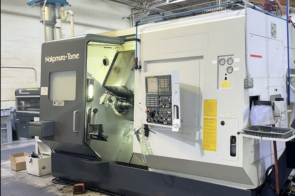
Technical Evaluation Guide: How to Identify a Quality Used, Secondhand, Pre-Owned, Surplus Nakamura Tome Super-Mill WY-250L CNC Dual Turrets Twin Spindle Multi-Axis Turning/Milling Center made in Japan
1) Machine Overview & Reference Specifications
Before visiting, obtain the original spec sheet or catalog for that exact machine unit. Below are key published specs and features for the WY-250L as a baseline.
| Feature | Published Spec / Capability |
|---|---|
| Max turning diameter | 225 mm |
| Max turning length | 910 mm |
| Distance between spindle noses | Up to 1,200 mm (max) |
| Bar capacity (L / R spindles) | L: 65 mm ; R: 51 mm (standard) |
| Spindle speeds | L / R up to ~4,500 / 5,000 rpm |
| Spindle motors (standard) | L: 18.5 / 11 kW ; R: 15 / 11 kW |
| Turrets / Tooling | Two turrets, each a 24-station dodecagonal drum turret; ~24 driven tool positions total |
| Y-Axis travel on turrets | ±50 mm (upper), –50 / +20 mm (lower) |
| Driven tool spindle | Up to 6,000 rpm, motor ~7.5 / 3.7 kW |
| Machine footprint / weight | Floor dimensions ~ 4,900 × 2,580 × 2,395 mm (L×W×H), weight ~13,000 kg |
These specs set your expected tolerances. Any candidate machine should be reasonably close unless documented modifications exist.
2) Pre-Inspection Document Request
Before going on site, ask the seller to supply:
- Original specification / build / configuration sheet
- Serial number, year of manufacture, and internal option history
- Maintenance / repair logs (spindle rebuilds, turret servicing, drive maintenance)
- Calibration / accuracy / metrology / alignment records
- CNC parameter backups, compensation tables, tool offsets
- Electrical / hydraulic / pneumatic / pneumatic / wiring diagrams
- Tooling and accessories list (live tooling, chucks, holders, steady rest)
- Any reports of crashes, collisions, retrofits or modifications
- Work history (typical parts machined, duty cycle)
This documentation helps you evaluate how far the machine may have drifted and what risk it carries.
3) Static / Visual Inspection (Power Off)
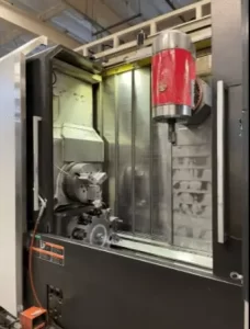
Walk around and carefully inspect all major structures and assemblies:
- Bed, frame & base: check for cracks, weld repairs, distortions, sagging, settling, or evidence of impact.
- Spindle housings / barrel / nose: inspect for corrosion, dents, wear on taper surfaces, cracks.
- Turret assemblies: open turret covers and check indexing cams, gripper fingers, pocket faces, backlash play.
- Guideways, slideways, rails: examine for scoring, pitting, rust, polished zones, uneven lubrication.
- Y-axis saddle / slide components: check for looseness, binding or wear in Y-actuation parts.
- Drive motor, gearbox, couplings: inspect for signs of wear, backlash, loose fasteners.
- Cable chains, harnesses, hoses: examine insulation, chafing, repairs, aging, broken links.
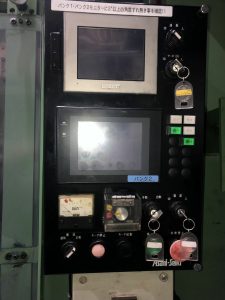
- Electrical cabinet: open and inspect wiring, burned insulation, capacitor bulge, dust; examine components’ condition.
- Coolant, lubrication lines & pumps: look for leaks, corrosion, cracked hoses, blocked lines.
- Safety doors, covers, interlocks: verify the presence and condition of guards, interlock switches.
Document all anomalies with photos; take close-ups of suspect areas (wear, rust, repair work).
4) Installation & Alignment Checks
If the machine is already mounted:
- Check machine leveling and foundation anchor points for settlement or shifting.
- Mount a reference test bar or indicator in one spindle in neutral turret position and measure radial runout at different positions along the carriage or turret reach.
- Jog X / Z / Y axes small increments to detect binding, sticky zones, or deviations.
- Perform turret indexing (upper & lower) and measure deviation of indexed tool carriers relative to spindle centerline.
- Check that Y-axis travel on both turrets is symmetrical and smooth, with no binding or tilt.
- If the machine has a B-axis (or rotary indexing), test its mechanical integrity and axis alignment.
5) Power-On & Motion / Functional Tests
With power and safety in place, perform these dynamic tests:
- Warm-up jogging: move axes (X, Z, Y) for ~20–30 min to stabilize lubrication and temperature.
- Homing / reference cycles: repeat referencing and ensure consistent return without limit trips or errors.
- Axis stroke test: jog X, Z, Y at various speeds (slow, medium, high) and listen / feel for irregular motion, binding or jerk.
- Turret indexing cycles: repeatedly index upper and lower turrets, check for mis-index, hesitation, or alarm errors.
- Spindle ramp-up / rotation: gradually accelerate both spindles (L & R) to operating RPM, monitor vibration, noise, smoothness, current draw.
- Simultaneous machining simulation: run a sample program using both spindles / turrets in tandem (if safe) to test synchronization and interference.
- Driven tool testing: spin the driven tools at rated speed (6,000 rpm) with light load, check for vibration or instability.
- Coolant / lubrication systems: engage coolant pumps, flush lines, check for leaks, stable pressure.
- Control / alarms: inspect alarm history, simulate minor fault conditions (e.g. limit switches) to ensure correct error detection.
- Encoder / feedback integrity: during motion, observe position feedback signals or readouts—check for dropouts or anomalies.
6) Accuracy, Repeatability & Metrology Tests
These tests distinguish whether the used machine is still precise enough:
- Use a laser interferometer or precision gauge to test linear positioning / straightness on X, Z, and Y axes.
- Perform backlash / reversal error tests: small ±0.01 mm moves in each axis and measure the difference when reversing direction.
- Repeat to a target position (e.g. 10×) and assess repeatability error.
- Repeatedly index turrets to the same tool station and measure tool location repeatability relative to spindle.
- Run a combined contour / interpolation test (turn + mill + Y-axis motion) and measure deviation from programmed path.
- After prolonged operation (≥1 hour), re-check reference positions to evaluate thermal drift.
- Conduct a hysteresis test: move to a position, dwell, return, and measure offset from original position.
- For long spindle reach / turret overhang positions, check accuracy near extremes, not just near center positions.
7) Spindles, Tooling & Wear Checks
- Mount a precision test bar and measure radial runout of each spindle nose / taper.
- Use vibration analysis or careful listening for bearing noise / hum at intermediate RPM.
- Run spindles continuously at moderate RPM for ~30 minutes and measure temperature rise.
- If internal spindles have drawbars or clamping, test retention / pull-out force.
- Validate taper or seating surfaces using dye / “blue” contact tests for even contact.
- Cycle tool changes (for live tool / turret tools) and verify tool offset repeatability.
- If milling heads or additional rotary / B-axis attachments exist, test their performance similarly (runout, vibration, repeatability).
8) Lubrication, Cooling, & Auxiliary Systems
- Confirm lubrication / oil / grease systems supply to all axes, turrets, spindles—check for blockages or leaks.
- Activate coolant systems, verify flow, pressure, filtration condition, and absence of leaks.
- Inspect coolant tanks, filters, piping for corrosion, sludge, or contamination.
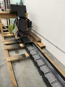
- Operate chip conveyors, swarf removal, guarding and check for smoothness and no jamming.
- Test any hydraulic / pneumatic actuators (e.g. turret locking, tailstock clamps) for pressure stability and leak-free performance.
- Verify control cabinet ventilation, fans, and that electronics remain cool during continuous operation.
9) Common Wear Modes & Red Flags
- Turret indexing wear, backlash or creep
- Y-axis mechanism play or binding
- Spindle bearing fatigue, vibration or runaway noise
- Tool change / gripper wear, inconsistent offsets
- Drive train backlash or nonuniform torque response
- Loss of lubrication, contamination of slides / rails
- Coolant leakage into critical mechanical areas
- Control / drive electronics aging: overheated components, failed boards
- Encoder feedback errors or dropout under motion
- Cable chain fatigue, insulation breakdown, connector failures
If multiple such issues are observed, the machine risk is high.
10) Acceptance Criteria & Benchmark Tolerances
Use this sample tolerance table as your “go / no-go” thresholds (tweak based on actual spec sheet and required precision):
| Parameter | Target / Acceptable Range |
|---|---|
| Linear axis accuracy (X, Z, Y) | ± 0.005 mm over moderate stroke |
| Backlash / direction reversal error | ≤ 0.01 mm |
| Repeatability (multiple cycles) | ± 0.005 mm or better |
| Turret / tool station repeatability | ≤ 0.01 mm |
| Spindle radial runout | ≤ 0.005 mm |
| Thermal drift (after 1 hr) | ≤ 5–10 µm shift |
| Tool offset consistency | ≤ 0.01 mm variation |
| Drive / servo current stability | Smooth curves, no spikes |
| Noise / vibration at rpm | Minimal, no bearing whine peaks |
| Coolant / lube stability | No significant drop under load |
If the machine fails several key benchmarks (especially spindle, turret repeatability, accuracy), it becomes a risky candidate or will require full refurbishment.
11) Buyer’s On-Site Quick Inspection Checklist
- Confirm serial number, build year, model variant
- Compare spec sheet vs actual travel, spindle, tooling features
- Perform visual inspection: bed, turrets, spindles, rails
- Jog axes (X, Z, Y) to feel for motion uniformity
- Cycle turret indexing repeatedly
- Ramp spindles, measure runout / listen for noise
- Run a small combined turning + milling test (if feasible)
- Accuracy / repeatability / drift tests
- Coolant, lubrication, chip systems functional
- Boot CNC, review alarm logs, ensure parameter backups
- Walk away if too many serious defects or missing documentation