Technical Evaluation Guide: How to Identify a Quality Used, Secondhand, Pre-Owned, Surplus Mori Seiki NL2500MC/700 CNC Turning Center made in Japan
1) Machine Overview & Baseline Specs
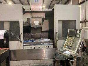
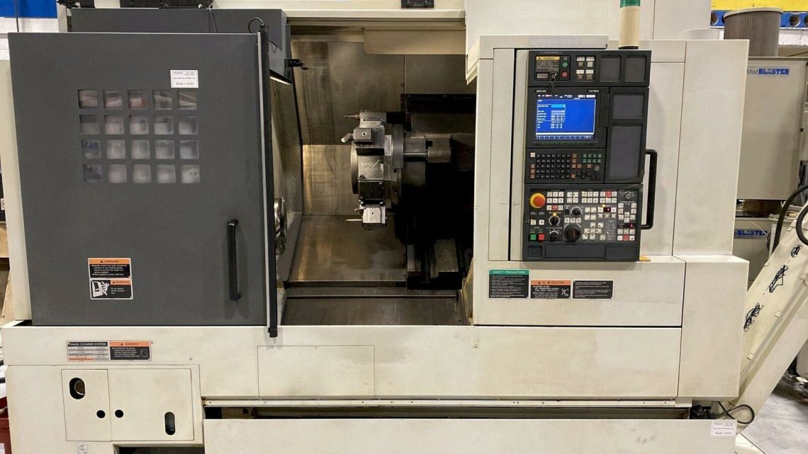
Before visiting the site, get the official specification sheet for the exact unit you will inspect. Here are representative specifications for the NL2500MC/700 (or similar NL2500 MC models):
| Feature | Typical Value / Published Spec |
|---|---|
| Swing over bed | ~ Ø 520 mm |
| Swing over cross slide | ~ Ø 310 mm |
| Maximum turning length | ~ 700 mm (680-750 mm) |
| X-axis travel | ~ 250 mm |
| Z-axis travel | ~ 700 mm (or 700 mm “700” suffix) |
| Spindle bore / bar capacity | ~ Ø 52–65 mm (model variant dependent) |
| Spindle speed | Up to 3,500 rpm (some variants) |
| Spindle motor power | ~ 22 / 30 kW (depending on variant) |
| Turret / live tooling | Often equipped with driven tools or Y-axis options |
| Rapid feed rates | ~ 36–42 m/min (varies by axis and variant) |
| Tailstock / steady rest (if included) | Provided in some configurations |
These spec values provide a reference to judge how close the used machine’s actual performance should remain.
2) Documentation & Pre-Inspection Requests
Ask the seller to provide, prior to the site visit:
- Serial number, manufacture year, and complete build / configuration sheet
- Past maintenance / service logs (major repairs, spindle rebuild, axis servicing)
- Calibration, geometry, or test reports (e.g. ballbar, laser)
- CNC control version, software revisions, backup of parameter files
- List of toolings, driven tools, turrets, and attachments
- Electrical, hydraulic, and pneumatic schematics
- Any modifications, retrofits, or repair history
- Alarm / fault history from the control
These documents help you establish what is reasonable wear and what is likely over-stressed or abused.
3) Static & Visual Inspection (with Power Off)
Before energizing the machine, examine:
- Frame & base / castings: Check for cracks, weld repairs, distortions, or signs of structural shock.
- Way covers / bellows / guards: Inspect for tears, missing sections, chip ingress, hardened deposits.
- Turret / tool changer assembly: Inspect turret indexing face, tool pockets, gripper arms, wear marks or looseness.
- Spindle nose / taper / barrel: Look for corrosion, scoring, dents, wear marks.
- Guideways / slides / cross-rail surfaces: Examine for gouging, pitting, polished zones, uneven lubricant traces.
- Tailstock / steady rest (if present): Check alignment surfaces, mounting integrity.
- Coolant / piping / hoses / fittings: Look for leaks, brittle hoses, past repairs.
- Cable carriers / wires / wiring harnesses: Inspect for damaged insulation, chafing, repairs, exposed conductors.
- Electrical cabinet & wiring: Open and visually inspect for burnt components, discoloration, dust, modifications.
- Safety interlocks, doors, covers: Verify precautionary mechanisms are intact and switches are present.
Document any wear or damage you find as photographic evidence.
4) Installation & Alignment Checks
If the machine is semi-mounted or in place:
- Check machine leveling and anchoring (shim stacks, base leveling)
- Use a test bar or spindle indicator to measure spindle radial runout in neutral orientation
- Jog X and Z axes small increments manually and watch for binding, stiffness, or noise
- Attach a dial indicator from turret face referencing spindle centerline; index turret to multiple positions and inspect deviation
- If a steady rest is present, mount a bar and check that the rest aligns with spindle axis without significant offset or misalignment
5) Power-Up & Dynamic Motion Tests
With power applied and proper safety measures:
- Warm up axes via jogging motion for ~20–30 minutes to stabilize lubrication and temperature
- Home / zero return cycles — check consistency and absence of limit or reference errors
- Move X, Z axes at various feed rates (25%, 50%, 100%) and listen for chatter, binding, or irregular motion
- Cycle turret through all stations multiple times; record indexing accuracy, any stalls or mis-index events
- Ramp up spindle from low to maximum rated rpm; monitor vibration, noise, current draw, temperature behavior
- Execute tool changes repeatedly to test magazine and gripper reliability
- Activate coolant & lubrication systems; verify flow, pressure, absence of leaks
- Observe encoder feedback and servo signals during axis motion; check for dropouts or encoder errors
- Review alarm log and fault history in CNC; verify no persistent errors or flagged faults
6) Accuracy, Repeatability & Metrology Tests
These are critical to determine the machine’s usable precision:
- Linear positioning / straightness tests (X & Z axes) using laser interferometer or precision displacement gauge
- Backlash / reversal error tests: ±0.01 mm moves back and forth; measure direction reversal error
- Repeatability: Move to a point repeatedly (e.g. 10×) and measure deviation in return
- Turret index repeatability: Index turret repeatedly to same station and measure deviation of tool location
- Combined turning + milling (if live tooling present): Run a test program combining turning and milling features; measure deviations in holes, external features, surface finish
- Thermal drift / stability test: Run machine under moderate load for 1–2 hours and then re-measure reference features to check drift
- Hysteresis / drift test: Move to position, dwell, return, measure offset
7) Spindle, Tooling & Wear Checks
- Spindle runout & vibration: Mount a precision test bar and measure radial runout; optionally use a vibration analyzer to detect bearing anomalies
- Spindle bearing noise / hum: At mid rpm, listen carefully for abnormal sounds
- Spindle temperature rise: Run spindle for ~30 min at moderate RPM; measure temperature drift
- Tool retention / pull-out test (if applicable): Test retention force or torque depending on tool-holder mechanism
- Taper seating / contact check: Use blue / dye or visual test to see whether taper seating is uniform
- Tool change repeatability: Repeated tool changes should result in consistent offsets
8) Lubrication, Cooling & Auxiliary System Inspection
- Coolant system: Check pump flow, pressure, clarity, leaks, piping; inspect filters and coolant tank condition
- Lubrication / grease / oil distribution: Verify that all axis lubrication lines are active and no blockages, leaks, or dry areas
- Chip removal / conveyor / coolant return systems: Run conveyor and coolant return systems to verify proper operation
- Hydraulic / pneumatic circuits: (If used) test valve behavior, pressure stability, leaks, responsiveness
- Filtration systems / tramp oil removal: Check filters, screens, separators, cleanliness
- Control cabinet ventilation / fans: Verify cooling is working, no excessive heating in control drives
9) Wear Modes & Common Failure Indicators
- Worn or scored guideways or gibs
- Turret indexing wear or slop
- Spindle bearing fatigue leading to vibration, runout
- Tool change gripper wear, magazine misalignment
- Coolant leaks into bearings or ways
- Inadequate lubrication or blocked lube lines
- Control or servo drive aging (fault logs, heat damage)
- Encoder or sensor feedback errors or dropout
- Cable harness fatigue, coolant ingress, poor wiring maintenance
10) Acceptance Criteria & Target Tolerances (Benchmarks)
Below is a sample tolerance table you can use as a benchmark (adjust according to the spec sheet):
| Parameter | Target / Acceptable Tolerance |
|---|---|
| Linear positioning accuracy (X, Z) | ± 0.005 mm over moderate stroke |
| Backlash / reversal error | ≤ 0.01 mm |
| Repeatability | ± 0.005 mm or better |
| Turret indexed tool repeatability | ≤ 0.01 mm deviation |
| Spindle radial runout | ≤ 0.005 mm |
| Thermal drift over 1 hour | ≤ 5 µm |
| Tool change offset repeatability | ≤ 0.01 mm |
| Coolant / lubricant stability | No significant pressure drop |
| Servo / load current stability | Smooth, no spikes |
If the candidate fails multiple of these tolerances, that machine may need refurbishment or be a higher risk buy.
11) Red Flags / Walk-Away Conditions
- Turret mis-indexing or repeated indexing errors
- Excessive spindle vibration or bearing noise at any rpm
- Repeated servo / axis faults in the CNC alarm log
- Tool change failures or inconsistencies
- Leaks of coolant or lubricant into way systems or bearings
- Worn guideways, scoring, or degraded surfaces beyond repair range
- Missing or corrupt CNC parameter backups / configuration files
- Control / drive overheating, visual damage to boards or power supplies
- Unexplained repairs or crash histories with no documentation
12) Buyer’s On-Site Quick Checklist
- Verify serial number, build year, and configuration
- Compare spec sheet to actual travel, spindle, tooling features
- Visual inspection: frame, ways, guards, covers
- Jog axes (X, Z) and observe smoothness
- Cycle turret indexing repeatedly
- Ramp up spindle and evaluate runout / vibration
- Accuracy / repeatability / drift checks
- Coolant, lubrication, chip systems operational
- Control boot-up, alarm logs, parameter backups present
- Walk away if multiple serious issues are found