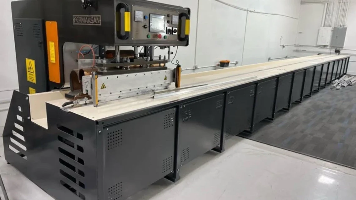
Technical Evaluation Guide: How to Identify a Quality Used, Secondhand, Pre-Owned, Surplus FERMAKSAN High Frequency PVC Welding Machine Table 14 Meters made in Türkiye
1) Key Specifications & Benchmark Expectations
Before visiting, obtain from seller the original specs or datasheet for the specific 14 m table model: electrode length, power rating, frequency, table dimensions, drive / motion type, welding head design, electrode gap, pressure system, etc.
Typical features you should benchmark:
- Welding length: ~14 meters electrode / upper bar travel
- HF generator power rating: e.g. in the tens to hundreds of kVA, frequency ~27.12 MHz or a standard HF plastic welding frequency
- Electrode gap / maximum stroke: the maximum opening distance between upper electrode and table for clamping thickness + margin
- Table dimensions / table bed structure: the width, support rails, rigidity
- Drive / motion system: linear rails, ball screws, servo/stepper drives for longitudinal motion
- Pressure / pressing system: hydraulic or pneumatic pressing, platen / electrode force control
- Cooling / dielectric / electrode cooling / water circuits
- Control system & interface: PLC / HMI, control logic for motion, dwell, welding timing
Use these spec values as your target reference. Any deviations should be understood relative to original design or modifications.
2) Document & Record Checklist (Before Arrival)
Request the following from the seller:
- Original specification sheet / datasheet (electrode length, power, frequency, motion parameters)
- Serial number, manufacture year, model designation
- Maintenance / service logs (generator servicing, electrode maintenance, drive repairs)
- Calibration / test records (weld quality, alignment, electrode gap consistency)
- Electrical schematics, wiring diagrams, control logic (PLC / motion interface)
- Spare parts list (oscillator tubes, electrode bars, motion components)
- Alarm / fault history logs
- Any modification / retrofit records (generator upgrades, motion system changes)
These documents help you judge how much the machine may deviate and identify non-original parts.
3) Visual & Static Inspection (Power Off)
Walk around and visually inspect all major parts:
- Bed / frame / table support structure: check for weld repairs, cracks, sagging, fatigue, corrosion in long spans
- Tables / rails / guide systems: inspect alignment, wear on rails or bed supports, signs of binding or deformation
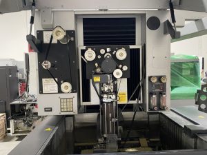
- Upper electrode bar / platen / pressing head: look for surface wear, corrosion, bending, damage in electrode surfaces or holder
- Electrode guides / insulating supports: check for wear, cracking, insulator damage, misalignment
- Drive trains (ball screws, linear guides, couplings) over the full 14 m: inspect for visible wear, backlash, play
- Hydraulic / pneumatic press components: cylinders, hoses, seals—check for leakage or past repair evidence
- Cooling / water circuits / plumbing: hoses, pipes, connections, valves for leaks, corrosion, brittle lines
- Electrical cabinets / enclosures: open panels, inspect wiring, signs of overheating, corrosion, modifications, cleanliness
- Motion cable carriers, drag chains, flexible conduit: inspect for wear, broken links, fatigued insulation
- Safety covers / guards / interlocks: confirm guards are present, doors function, interlock switches in place
Photograph any anomalies, repairs, or evidence of previous impacts.
4) Installation & Alignment Checks
If the machine is already mounted or partially installed:
- Confirm that the table is level over its full length—check for rolls or twist using precision levels or straightedge
- Inspect anchoring or foundation mounting to ensure the machine is not subject to bending or stress
- Using a reference rail or straight edge, check longitudinal alignment of the electrode / motion direction
- Check that the electrode bar / platen slides or moves uniformly along its full length without binding
- Place a dial indicator at multiple points along the electrode length; test for parallelism to table surface / bed
5) Power-Up & Motion / Functional Tests
With power and safety measures active:
- Warm up the motion system via jogging the electrode carriage or welding head for ~20–30 minutes
- Home / reference return sequence: check repeatability of home positions, no limit errors
- Drive test: move the electrode carriage full 14 m at different speeds (slow, mid, fast), watch and listen for binding, jerkiness, or motor strain
- Press / pressing head motion: test the upper electrode elevator / press downward stroke, check smoothness and consistency
- Generator output simulation (if safe to energize): test the HF generator without load or with test material to see stable output and no spark misfires
- Timing / dwell test: run a mock welding cycle to verify correct dwell time, electrode contact, motion timeline
- Electrical / controls: test PLC / HMI inputs, outputs, interlocks, emergency stops, parameter setting, alarm panels
- Cooling / water circuits: run coolant / electrode cooling water flow, check for leaks or pressure drops
- Pressure system: pressurize hydraulic / pneumatic press, monitor pressure stability, no leaks
6) Weld Accuracy, Uniformity & Reproducibility Tests
This is the core component for HF PVC welding:
- Place standard test sheets or PVC material and perform test welds over full electrode length (long seams). Inspect weld uniformity—consistency of weld bead, seam strength, visual appearance
- Weld seam quality across length: inspect that weld is continuous, no cold joints, dropouts, or weak spots
- Electrical / HF current uniformity: use measurement probes to check that generator current / power is stable and uniform across electrode length
- Electrode gap stability: test initial gap and check whether drift occurs over repeated passes
- Pressure uniformity: ensure pressure is consistent along the electrode length (press force control)
- Thermal consistency: after extended welding, verify that the electrode / platen temperature remains within acceptable bounds—no thermal warping
- Cycle repeatability: repeat the same weld program multiple times and measure consistency in weld quality, bead dimensions, power draw
7) High-Frequency Generator & RF Components Checks
- Inspect the generator power module, tank circuit, oscillation tube (if used), capacitors, matching network for obvious wear, discoloration, or overheating
- Verify RF cable / transmission lines / connectors between generator and electrode – no corrosion, cracks, loose fittings
- If applicable, examine the arc suppressor / spark protection tube for condition and functionality
- Test the generator under dummy load (or calibration standard) to verify stable output, correct frequency (e.g. 27.12 MHz) and no drift
- Monitor the generator’s current draw and voltage during test cycles for anomalies
- Check cooling of generator / RF modules: fans, heatsinks, coolant jackets (if applicable)
- Inspect matching networks, inductors, capacitors, tuning circuits for loose parts or signs of arcing
8) Lubrication, Cooling, Water & Auxiliary Systems
- Cooling / water systems: flow rate, pressure, no leaks, cleanliness of coolant, check for contamination
- Electrode / platen cooling circuits: ensure water or coolant flow to electrode holders, no blockages
- Hydraulic / pneumatic systems: check pressurization, leakage, actuator response
- Filtration / water filtration / strainers / traps: ensure filters are clean, no clogged lines
- Cabinet & component cooling: ensure that enclosures, fans, ventilation are working, no overheating
- Lubricant systems (for motion carriage): confirm grease / oil delivery to rails, screws, check blocked lines, dry spots
9) Common Wear, Failure Modes & Red Flags
- Electrode bar bend, warping, or deformation
- Nonuniform motion / binding in long carriage travel
- Generator component failure (capacitors, tubes, matching network)
- RF line leakage, breakdown, connector faults
- Pressing head misalignment or press actuator wear / leaks
- Thermal drift or heating causing electrode misalignment
- Motion drive backlash or looseness over long span
- Cooling / water leakage damaging insulating or structural components
- Control electronics failure, PLC faults, parameter corruption
- Cable harness fatigue, connector corrosion
If multiple of these appear, the machine risk is high.
10) Acceptance Criteria & Benchmark Targets
Use these sample tolerance guidelines (adjust based on datasheet):
| Parameter | Target / Acceptable Tolerance |
|---|---|
| Electrode carriage positioning repeatability | ± 0.1 mm (for 14 m motion) |
| Motion smoothness / no binding | Fully smooth travel, no vibration |
| Press stroke repeatability | Very tight repeatability each cycle |
| Weld seam quality consistency | Visually uniform along full length + mechanical test |
| Generator frequency stability | ± < 0.5 % from nominal |
| Generator output stability | No major fluctuations during cycle |
| Electrode gap drift over cycle | Minimal drift (< 0.1 mm) |
| Thermal stability over extended use | Minimal drift or deformation |
| Cooling / water pressure drop | Within spec, no major drop |
| Motion drive current stability | Smooth current traces, no spikes |
If the unit fails several of these benchmarks, it is not ideal without refurbishment.
11) Buyer’s On-Site Quick Checklist
- Serial number, model, and datasheet confirmed
- Full length of electrode motion tested for smoothness
- Press head motion and pressure system tested
- Generator output test (dummy / no-load)
- Weld test across full length with material
- Repeatability of weld and motion cycles
- Cooling / water / hydraulic / pneumatic systems operating
- Inspection of RF / electrical / motion drive components
- Control / PLC / HMI interface tested
- Walk away if serious defects, structural issues, or generator instability