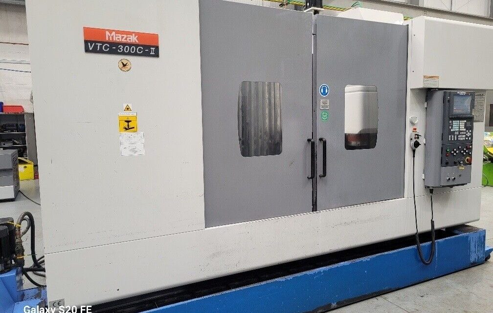
Technical Evaluation Guide: How to Identify a Quality Used, Secondhand, Pre-Owned, Surplus Mazak VTC-300C-II CNC Vertical Machining Center made in Japan
1. Know the “Golden Baseline” (Spec Sheet) — What to Expect
Before inspection, you should carry with you the factory / typical reference specifications for the VTC-300C-II (or VTC-300C family) so you can spot deviations. Here’s a summary of typical specification values drawn from listings, catalogs, and used-machine inventories:
| Parameter | Typical / Nominal | Notes / Source |
|---|---|---|
| X travel | ~ 1,740 mm (≈ 68.5″) | |
| Y travel | ~ 760 mm (≈ 30″) | |
| Z travel | ~ 660 mm (≈ 26″) | |
| Table size | 2,000 × 760 mm | |
| Max table load | ~ 1,400 kg | |
| Spindle speed | up to 12,000 rpm | |
| Spindle motor power | ~ 18.5 kW | |
| Tool changer capacity | ~ 30 tools | |
| Spindle taper | CAT40 (BT40 / ISO 40) | |
| Control | Mazatrol “Fusion / PC Fusion 640M” | |
| Dimensions & weight | ~ 4,400 × 3,400 × 3,086 mm; ~ 11,500 kg | |
| Spindle-to-table clearance | 180 to ~ 840 mm |
Use those as baseline “red lines”: if the machine’s geometry or capacities deviate substantially, that may mean a misrepresented machine or serious wear.
Also be aware: some variant models (e.g., non-“II”, or machines with added options, alternative spindle upgrades, etc.) may vary. Always ask for the original factory spec sheet (or build sheet) from the seller.
2. Document Review & History
Before or during the physical inspection, collect and review documentation:
- Maintenance / service logs — ideally with dates, hours, parts replaced, vibration tests, alignment checks, spindle rebuilds, etc.
- Power-on / usage hours (if available): both the total hours and the cutting / load hours (if separated). Heavy usage increases wear risks.
- Repair / overhaul records — e.g. spindle rebuilds, ball screw replacement, structural repairs, crash events etc.
- Original factory drawings / manuals / build sheet — to confirm the original configuration, options, or retrofits.
- Parts list / BOMs / consumables used — to see whether the owner used OEM parts or cheap replacements.
- Controller / software history — what version of Mazatrol Fusion, any custom macros, backup logs, CNC program archives.
A machine with full, consistent, and verifiable logs is far more trustworthy than one with missing or vague records.
3. Visual & Structural Inspection
Begin with an unpowered, cold visual inspection. Many problems show up in the “skin” of the machine.
Exterior
- Look for cracks, weld repairs, distortions in the column, saddle, machine base, and guard structure.
- Surface corrosion, pitting, rust spots: especially on bed surfaces, guide rails, machine base, covers.
- Missing covers, way wipers, bellows, or guarding panels. If covers are missing, internal components may have suffered.
- Check the integrity of way covers / bellows — torn, misaligned, or bent covers allow ingress of chips/coolant.
- Evidence of coolant leaks (past or present) — stains, corrosion around fittings, pooling on floor, corrosion on panels.
Machine Structure & Alignment
- Straightness / squareness of major axes: You can use a long straightedge or optical methods (e.g. laser) to inspect deviations in the column or base.
- In many vertical machining centers, wear is pronounced in the Z axis guideways / ways or the saddle ways, especially if load cycles were heavy or lubrication neglected.
- Inspect base and foot mounting surfaces — distortions here can compromise alignment.
Bolts, Fasteners & Joints
- Check for missing, mismatched, or non-OEM bolts in key structural joints — indicates prior repair or parts scavenging.
- Check torque status of covers and guarding. If many deformed or over-torqued, the machine may have had rough handling.
Cable Trays, Wiring, Conduits
- Examine the exterior wiring, cable carriers, conduit, junction boxes: frayed wires, open conduits, exposed cables are red flags.
- Check for signs of overheating, charring, or discoloration on wiring insulation.
4. Mechanical / Kinematic Component Checks (Cold Tests)
Once visual inspection is done, move into mechanical checks (without powering the machine). Use hand tools, indicators, measuring devices, as appropriate.
Ball Screws, Linear Guides, and Slideways
- Move each axis (by hand or jog in “manual / low speed”) through its full travel, feel for binding, stiction, gritty motion, irregular resistance, backlash.
- Use a dial indicator (or test indicator) mounted to check backlash in each axis (e.g. reversing direction and measuring motion lag). Excessive backlash is a sign of worn nuts, ball screw wear, or drive train issues.
- With a gauge block or other precision standard, check flatness / straightness / pitch error along the travel.
- Inspect ball screw nuts for backlash, axial play, or evidence of wear.
- Inspect guideway surfaces (flat-bar, V-way, or box ways) for scoring, pitting, gouges, corrosion, or inconsistent wear patterns.
- Check lubrication system for each axis — are grease / oil lines intact, do they run cleanly, any blockages or dry spots?
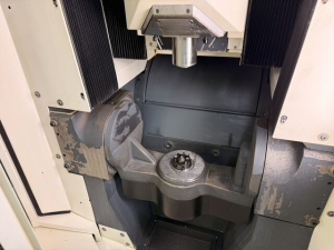
Spindle & Spindle Bearings
The spindle is often the most expensive component to repair or replace, so this deserves special attention.
- With the spindle off (or idle), insert a test tool holder (clean and fully seated). Rotate by hand and check for axial or radial play (wobble). There should be minimal to none.
- Use a dial indicator to check runout of the spindle nose or the tool holder tip (say at 100–200 mm extension).
- Request or perform a vibration test / bearing sound test at various speeds — listen/feel for abnormal noises (grinding, whine, growl). Bearing degradation often manifests first as noise or vibration.
- Observe how the spindle accelerates and decelerates (in powered test) — check for smooth ramping, no lag or misbehavior.
- Inspect spindle cooling and lubrication fittings, seals, and temperature history (if logged). Insufficient cooling / lubrication leads to bearing failure.
- Look at the spindle taper bore surface for scoring, burn marks, discoloration (heat damage), rust, or erosion. Use a “blue dye / spotting spray” test: insert a known good tool holder, lightly twist, then remove and inspect the contact pattern — it should be uniform and consistent.
- Check drawbar / retention mechanism: ensure it operates smoothly, without slop or failure to grip.
Tool Changer & Magazine
- Cycle the tool changer through its full motion, switching into each magazine station and back to spindle. Evaluate speed, smoothness, repeatability, alignment, and indexing accuracy.
- Watch for any collision, misalignment, hesitation, or refusal to load/unload certain stations.
- Inspect magazine rails, pivot bearings, gear teeth, cams, and actuators for wear, play, misalignment, or damage.
- Check magazine position sensors and mechanical limit switches: do they all register correctly and reliably?
- Measure the repeatability and accuracy of tool pick/place operations (e.g. measure the tool length probe return vs tool change, or compare tool offsets after multiple cycles).
Auxiliary Systems: Coolant / Chip Handling / Hydraulics / Pneumatics
- Inspect coolant system (tank, pumps, filters, piping, flush lines, nozzles). Check for contaminants, sludge, leakage, and pump health.
- Check chip conveyor, chip auger, coolant sumps, filters, separators, tramp oil removal. Run the conveyor and inspect for binding, worn belts, broken screws, or motor issues.
- Inspect hydraulic / pneumatic circuits if present (e.g., for tool clamping, workholding) — leakage, pressure stability, proper valves and plumbing.
- Check way lubrication / centralized lube system (if equipped) — are all lube points functioning, are oil reservoirs clean, is flow consistent.
- Test all axis brakers / safety interlocks, limit switches, emergency stops, guarding circuits.
5. Power-On / Dynamic / Operational Tests
With the machine powered (in a controlled, safe configuration), run through a sequence of dynamic tests to assess how the machine behaves in real use.
Control & Electronics
- Power up the CNC, check for alarm history, error logs, memory faults, or “disabled axes.”
- Test all major CNC functions: jogging, homing, zeroing, reference moves, macro functions, offset tables, probing routines, canned cycles, corner rounding / interpolation, etc.
- Load and run a simple test program to move the axes under no load — check for snappiness, no stalling, and consistent axis motion.
- Monitor the CNC display for errors, fluctuations in voltage, internal warnings, or temperature alarms.
- Check all operator panel keys, switches, screen responsiveness, MPG (manual pulse generator) operation, emergency stop, and Jog / MDI functions.
Axis Dynamics & Accuracy
- Use a test program to move axes (X, Y, Z) in pattern (e.g. “ladder” move, back-and-forth motion) while measuring with an indicator or laser tool to check positioning accuracy, repeatability, linearity.
- Perform a “box test” (e.g. move X, then Y, then X back, then Y back) and measure deviation from starting point.
- Check acceleration / deceleration smoothness. Monitor for signs of lost steps, jumps, or overshoot.
- Under light load, run a spindle-milling test (e.g. light cut on a soft material) and observe surface finish, chatter, noise, and dynamic behavior.
- Check thermal drift: let the machine run for a while, take measurements at start and after warming up to see how positional offsets drift with heat.
Spindle / Load Test
- Run the spindle through its full rpm range (e.g. up to 12,000 rpm) and monitor for abnormal vibration, noise, or overheating.
- Under light to moderate cutting load, test performance (ease of feed, cooling, no stalling). Observe chip evacuation, chatter, thermal stability.
- Watch temperatures of bearings, headstock, and electronics during extended runs.
6. Geometric & Alignment Verification
Even a structurally sound machine can drift in alignment over time. Verifying geometry is essential for precision work.
- Use a laser interferometer, ballbar tester, or autocollimator to check straightness, squareness, pitch error, yaw error, and linear deviations of the X/Y/Z axes.
- Check perpendicularity: for example, move in X and Z (or Y and Z) and measure if planes remain square.
- Check “flatness” of table surface via precision granite square or surface plate, with full travel in both X and Y.
- Measure for twist, bow, or sag in long travel runs.
- Compare measured geometry vs original spec (or factory tolerance) to assess the residual usable accuracy.
- If possible, inspect for “machine signature” or wear patterns — consistent deviations may be tolerable; erratic ones may imply abuse or prior crash damage.
7. Wear / Tolerance “Red Flags” to Watch For
Here are specific warning signs you must not (or should hesitate) accept without mitigation:
- Excessive backlash or play in axes that is beyond recoverable levels.
- Deep scoring, pitting, or excessive wear on guideways or ball screws.
- Spindle bearing noise, vibration, or inability to maintain tolerances at high rpm.
- Spindle taper with burn marks, uneven contact, or damaged surfaces.
- Tool changer misalignment, frequent tool load/unload errors, magazine stalls.
- Poor lubrication / dry zones / clogged lube system.
- Major corrosion, rust, or structural damage.
- Evidence of prior crash (e.g. dented ways, bent columns, replaced structural components).
- Control / CNC faults, memory errors, or inability to boot reliably.
- Thermal drift out of acceptable limits (especially if warm geometry shifts are large).
- Incoherent or missing maintenance history.
- Non-OEM parts or undocumented retrofits (unless verified thoroughly).
8. Cost Estimation of Repairs & Upgrades
Even a good used machine often needs “refresh” or spare parts. Before purchase, estimate:
- Potential cost to rebuild or replace spindle bearings or spindle unit if needed.
- Cost to re-scrape or realign guideways / slide surfaces.
- Cost of ball screw nut replacement or regrinding.
- Control / electronics refurbishment, replacement of drives, motors, CNC boards.
- Replacement of covers, wipers, cables, cooling system, hydraulics.
- Shipping, rigging, reinstallation, calibration and verification at your site.
Negotiate price accordingly, leaving margin to cover these potential expenses.
9. Final Acceptance / Warranty Conditions
If possible, negotiate a short acceptance period or “run-in / burn-in” period after installation in your facility, during which the seller remains liable for hidden defects.
Also request that the seller demonstrate the machine under (pseudo) production conditions, provide as-is test cuts, and sign off on axis accuracy. If possible, bring your own test parts or measuring instruments.
Checklist Summary
Here’s a condensed checklist you can bring to inspections:
- Spec conformance (travel, spindle, table, speeds)
- Documentation: logs, maintenance history, rebuilds
- Exterior / structure: cracks, corrosion, missing covers
- Guideways / ball screws: smooth motion, backlash, wear
- Spindle / bearings: play, vibration, taper condition
- Tool changer / magazine: indexing, repeatability, wear
- Auxiliary systems: coolant, chip handling, lubrication
- CNC & electronics: full functions, errors, responsiveness
- Dynamic tests: axis motion, load cuts, thermal drift
- Geometric alignment: straightness, squareness, linear error
- Red flags: crash evidence, missing parts, undocumented mods
- Repair cost estimates and negotiation buffer
- Acceptance / warranty / test run agreement