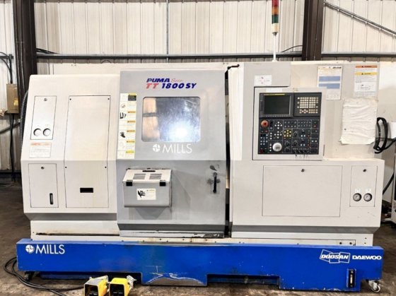
Technical Evaluation Guide: How to Identify a Quality Used, Secondhand, Pre-Owned, Surplus Doosan Puma TT1800SY CNC Turning Center made in South Korea
1. Baseline Specifications & Key Features (What to Expect)
Before you inspect, you should have (or ask the seller for) the original specification / build sheet so you know what the machine should be. Here are typical specs / features for the TT1800SY (drawn from used-machine ads and manufacturer product pages) to use as reference:
| Parameter | Typical / Nominal | Notes / Sources |
|---|---|---|
| Chuck / Bar capacity | 8 in (≈ 230 mm) | DN Solutions spec page |
| Max turning diameter | ~ 230 mm (9 in) | |
| Max turning length | ~ 230 mm (9 in) | (depending on variant) |
| X travel | (Upper / Lower turrets) — typical ~ 165 mm | |
| Y travel | ~ 100 mm | |
| Z travel | ~ 700 mm | |
| Rapid traverse speeds | ~ 787 ipm in X, ~ 944 ipm in Z (or metric equivalent) | seen in used listings |
| Spindle speed | 5,000 rpm | Many listings list 5,000 rpm spindles |
| Spindle power / motor | ~ 30 hp (≈ 22 kW) | Several ads list 30 hp for main / sub spindles |
| Turret configuration | Upper + lower turrets, often each 24 stations (total ~48) | Many used ads list “24 + 24 (48 total)” turret config |
| Indexing / turret time | ~0.15 seconds | In used ads |
| Sub-spindle / C-axis, live tooling, Y-axis | Many variants include sub-spindle, C-axis indexing, live tools, Y axis | Ads often mention “dual spindle / dual turret / Y axis / live tooling” capabilities |
| Control system | Likely Fanuc or Doosan proprietary / hybrid control (Fanuc 31i etc.) | Some used ads mention Fanuc 31i or other Fanuc variants |
Why this matters: If the actual machine deviates significantly from these, either it’s a different variant, some features have been removed or modified, or it’s misrepresented. Always compare to the build sheet.
Also note that the “SY” suffix often indicates “Sub-spindle / Y axis” or more advanced multitasking capabilities.
2. Document & History Review
Before stepping into the shop floor, request and review the machine’s paperwork:
- Original build sheet / factory spec document — confirms exactly which options (live tooling, Y-axis, sub-spindle, coolant, chiller, robot interface etc.) were supplied.
- Service / maintenance logs — ideally showing dates, hours, parts replaced, spindle rebuilds, alignment verifications, vibration tests, overhaul events.
- Operating hours — total hours, and if possible the “cutting hours” separately (idle hours vs under load).
- Repair / modification history — e.g. turret rebuilds, spindle replacement, crash repairs, retrofits.
- Control / CNC backups — program archives, parameter backups, version history.
- Parts / consumables usage records — whether OEM or non-OEM parts were used.
- Calibration reports — past laser, ballbar, alignment or geometric measurement reports.
A machine with consistent, detailed, credible documentation is far safer to evaluate than one with vague or missing history.
3. Visual / Structural Inspection (Cold)
Start with a cold, unpowered inspection. Structural, cosmetic, and external faults often reveal underlying issues.
Exterior & Structure
- Look for cracks, weld repairs, distortions in the bed, headstock, turret supports, saddle, column (if any), base, and frame.
- Inspect for surface corrosion, pitting, rust — especially on rails, guideways, turret faces, dovetail surfaces, tool slide faces.
- Check whether guarding, covers, way wipers, bellows, chip guards, splash guards are present and intact. Missing or damaged covers often allow ingress of chips, coolant, abrasives.
- Examine cable carriers, hoses, wire conduits: fraying, abrasion, exposed wiring is a red flag.
- Look for signs of coolant leaks (stains, residue, corrosion) around pumps, piping, fittings, around turret base, under machine.
- Inspect the turret faces and turret body for any misalignment, deformation, gap, or signs of prior hit / repair.
Turrets & Tooling Mounts
- Check the turret faces for wear, pitting, or damage at the tool pocket seating surfaces.
- Look for uneven surfaces or mismatches of tool pocket geometry.
- Inspect turret indexing drives, cam faces, indexing motors, gripper arms, sensors, and mechanical limit switches.
Spindle Housings & Chucks
- Inspect spindle nose surfaces for corrosion, wear, rust, or signs of heat damage.
- Look at the mounting for collet chucks, backplates, roots of spindle, any weld repairs or machining modifications.
- Inspect sub-spindle (if present) similarly.
Fasteners, Joints, Access Covers
- Check that all major structural fasteners are original, intact, properly torqued — no missing, mismatched, or jury-rigged bolts.
- Access covers should open/close properly; hinges, seals, gaskets should be intact.
- Check for signs of mishandling or bending / misalignment in covers or frames.
4. Mechanical / Kinematic Checks (Cold / Manual)
With the machine still powered off (but in a safe condition for movement), perform mechanical checks:
Slideways, Guides & Ball Screws
- Jog or move each linear axis (X, Y, Z, and any secondary axes) slowly and carefully through full travel. Feel for binding, sticking, gritty motion, “catch points,” or irregular resistance.
- Check for backlash by reversing direction and measuring lost motion. Excessive backlash may indicate worn ball screws, worn nut, or drive train weakness.
- Use dial indicators or test indicators to check straightness, flatness, and pitch error along axes.
- Inspect ball screw threads (worm / ball screw) for wear, marks, pitting, or damage.
- Check nut housings for looseness or play.
- Examine guide rails (linear guide blocks, roller guides, LM guides) for pitting, scoring, rust, or uneven wear patterns.
- Check lubrication supply points: are oil / grease lines intact, no blockages, and evidence that lubrication has been delivered.
Turret / Tool Change Mechanism
- Cycle the turret in indexing mode (by hand or slow jog) through all pockets. Observe motion: smoothness, stick/slip, hesitation, alignment.
- Listen/feel for any binding or missed indexes.
- Check turret locking actuators, clamp mechanisms, alignment pins, sensors, limit switches.
- Inspect drive coupling, gears, cams, and clutch systems (if applicable).
Spindle / Sub-spindle Bearings & Runout (Cold)
- Mount a known good toolholder or test bar (clean, well seated), rotate by hand or low rpm (if safe) and check for radial and axial play. There should be minimal to none.
- Using a dial indicator, measure runout at the tool tip or a known surface. Excessive runout is a red flag.
- Inspect the spindle taper surface for pitting, discoloration, corrosion, burn marks, uneven wear.
- Perform a “spot test” by applying a thin film of dye or marking compound, seating a toolholder lightly, rotating slightly, and pulling — the contact pattern should be uniform (i.e. consistent across the taper surface).
- Check drawbar mechanism, tool retention / clamping mechanism, and check whether it moves smoothly or has slop.
Auxiliary Systems (Coolant, Chips, Hydraulics)
- Inspect coolant system (pump, piping, nozzles, filters, sumps). Look for sludge, impurity, leaks, corrosion.
- Inspect chip conveyor / chip removal, chip augers, conveyors, belts, motors. Test whether they move freely.
- Examine hydraulic / pneumatic circuits (if present): cylinders, hoses, valves, pressure regulators, seals, leaks.
- Test the lubrication / grease / oil auto-lube system: whether all points are receiving lubricant, any dry zones, pump health.
5. Power-On / Dynamic / Functional Tests
Power up the machine (observing all safety procedures) and verify electronic, motion, and functional behavior under dynamic conditions.
Control & CNC Systems
- Power up the control, check for error alarms, fault logs, memory errors, disabled axes, parameter mismatches.
- Test all operator panel keys, touchscreen / display, overrides, MPG (manual pulse generator), emergency stop, jog/MDA/MDI modes.
- Execute homing cycles, reference moves, axis zeroing, offset functions.
- Load a simple motion program (no load) to move all axes in combination (X, Z, Y, any secondary axes) and verify smooth motion, no stalling, no alarms.
- Check if all limit switches, interlocks, safety circuits, guards, door sensors, etc., are functioning.
Axis Motion & Accuracy Under Power
- Run a “box motion” or grid motion test: move in X, then Z, then return, then combine motion, and measure deviation from start point (using indicator or laser).
- Test positioning accuracy and repeatability (e.g. move to a point multiple times, measure deviation).
- Monitor axis acceleration and deceleration behavior for overshoot, jerk, or instability.
- Test under light cutting load (soft material) to see dynamic behavior (vibration, chatter, stability).
Spindle Performance & Under Load Test
- Ramp spindle from low rpm to high rpm (e.g. up to ~5,000 rpm) and back, listening for bearing noise, vibration, abnormal sound.
- Monitor temperature of spindle housing, bearings, headstock area during use.
- Apply a light cutting load (in soft material) and observe how it holds rpm, whether torque dips, whether overheating or chatter arises.
- Check spindle torque consistency, power draw, acceleration under load.
- Verify tool changing operations under full control: tool change cycles, turret indexing, tool pick / place motions — they should be smooth, reliable, repeatable.
Simultaneous / Multitask Operations
Because TT1800SY is a multitask machine (dual turrets, possibly dual spindles, Y axis, live tooling), test simultaneous operation:
- Run both turrets (upper & lower) simultaneously in different operations, e.g. face on one turret while OD turning on the other, and check interference, synchronization, stability.
- Test sub-spindle handoff (if present) — check part transfer, chucking/un-chucking operations, timing, alignment.
- Test any live tooling / milling functions: start up, at speed, under light load, monitor vibration, verify tool stability.
- If Y-axis is present, test cross-axis motion (e.g. tool moving off-center), verify Y-axis backlash, responsiveness, stability.
6. Geometric / Alignment Verification
Precision and accuracy depend on maintaining proper geometry. Use metrology tools (laser interferometer, ballbar, autocollimator, granite squares) to verify:
- Straightness of X, Z, Y axes over full travel.
- Squareness / perpendicularity: e.g. move in X then Z, measure if motion plane is flat.
- Pitch error, yaw error, linear deviation, pitch variation, taper errors.
- Check concentricity of both spindles (main / sub) relative to bed / axes.
- Check alignment between upper and lower turrets (that both tool axes are coplanar / aligned).
- For sub-spindle, check coaxial alignment between main and sub when handing off parts.
- Measure turret face runout / alignment of pocket seats.
- Compare measured geometries to machine tolerance or original spec — a small deviation is tolerable; large or erratic ones are red flags.
7. Key “Red Flags” & Warning Signs
When inspecting, watch closely for:
- Excessive backlash in axes or turret drive which cannot be corrected reasonably.
- Severe wear, pitting, scoring, or corrosion on guideways, ball screws, turret faces, spindle taper.
- Spindle bearing noise / vibration / wobble — signs of worn bearings or impending failure.
- Uneven taper contact or damage on spindle nose, meaning poor tool seating.
- Turret indexing errors, alignment errors, hesitation or failure to index in some pockets.
- Failed or intermittent electronics / control errors / parameter mismatches — frequent alarms or instability.
- Poor motion under dynamic load: chatter, instability, lost steps, stalling.
- Severe thermal drift — geometry changing significantly during warm-up period.
- Missing covers, damaged way wipers / bellows — internal components may be exposed to contamination.
- Evidence of crash / impact damage — distorted frames, bent parts, weld repairs.
- Non-OEM or undocumented modifications that alter structure, axis limits, or safety.
- Unreliable or missing maintenance / service logs — lack of traceability.
- Hard-to-source parts (if exotic or deprecated components) — may hamper repairs.
If any of these are present, demand mitigation (repair, discount, warranty) or consider walking away.
8. Repair / Refurbishment Cost Estimation & Risk Buffer
Before making an offer, budget for potential restoration tasks:
- Spindle bearing replacement or spindle refurbishment.
- Ball screw nut replacement or regrinding.
- Re-scraping or realignment of guideways.
- Turret rebuild (index drives, cam surfaces, grippers).
- Replacement of covers, bellows, wipers, cable carriers.
- Control / electronics overhaul, drive / motor replacements.
- Calibration, laser alignment, geometry measurement, certification.
- Shipping, rigging, installation and test at your site.
Leave a margin in your negotiation to cover these likely costs.
9. Acceptance, Test Runs & Risk Mitigation
To reduce your risk, do the following as part of your purchase agreement:
- On-site test run / “warm-up / burn-in” period (e.g. 8–24 hours) under light production conditions to reveal latent issues.
- Acceptance criterion: axis accuracy, spindle behavior, part machining test (run a sample part).
- Guarantee / warranty clause for major components (spindle, turret, drives) for a short period post-installation.
- Require as-is test cuts before purchase; ideally bring your own sample workpiece and measuring tools.
- Third-party inspection: hire a trusted machine-tool inspector or metrology service to validate your findings.