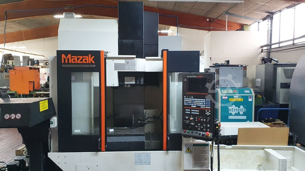
Technical Evaluation Guide: How to Identify a Quality Used, Secondhand, Pre-Owned, Surplus Mazak Vertical Center Smart VCS 430A CNC Vertical Machining Center made in Japan
Reference / Typical Specifications — What “Normal” Looks Like
Before inspection, obtain the factory build / spec sheet for that particular unit (serial / options). Use it to cross-check what you find. Here are published specs of a Mazak VCS-430A as a baseline:
| Spec | Typical Value (from used listings) |
|---|---|
| X travel | 22.05 in (≈ 560 mm) |
| Y travel | 16.93 in (≈ 430 mm) |
| Z travel | 20.08 in (≈ 510 mm) |
| Table size | 35.43 in × 16.93 in (≈ 900 × 430 mm) |
| Spindle speed | 12,000 rpm |
| Spindle motor / power | 25 HP |
| Spindle taper | CAT-40 (Mazak #40 / “SK-40” style) |
| Tool magazine capacity | 30 tools |
| Rapid traverse (all axes) | ~ 1,653 in/min (≈ 42 m/min) |
| Minimum / maximum spindle nose to table | ~ 5.91 in / 25.98 in |
| Machine weight / footprint | ~ 10,142 lbs (≈ 4,600 kg); dims ~103.29″ × 81.89″ × 109.37″ |
Use these as “checkpoints.” If the machine you inspect diverges sharply (e.g. lower spindle speed, fewer tools, much lower travel), confirm it is a variant or that components have been swapped or downgraded.
Inspection Workflow & Key Checks
Below is a recommended step-by-step protocol. You may adapt for access constraints.
1. Review Documentation & History
Begin by collecting and validating as much documentation as possible:
- The original build specification / configuration sheet (options, axes, control, accessories).
- Maintenance and service logs: spindle rebuilds, alignment / geometry checks, lubrication schedule, repairs.
- Operating hours, especially cutting hours vs idle time.
- Records of component replacements (spindle, axes, toolchanger, control modules).
- Calibration / metrology reports (if available) — e.g. straightness, backlash, runout checks.
- Tooling, fixtures, spare parts included.
- Control / CNC backups, parameter files, alarm logs, error history.
If documentation is poor or missing, your risk increases — lean more heavily on empirical testing.
2. Visual / Structural / Cold Inspection
With the machine powered off, inspect external and accessible parts. Many serious issues show up visually.
- Frame, base, column, casting: check for cracks, welds, distortions, misalignment, surface corrosion, pitting.
- Guideways / slides on X, Y, Z axes: inspect for scoring, scratches, corrosion, uneven wear patterns.
- Protective covers, bellows, wipers: ensure they’re intact and functioning (missing or damaged covers allow debris ingress).
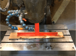
- Spindle nose / taper: check for pitting, dents, corrosion, uneven wear.
- Spindle housing, bearing covers, seals: look for oil leakage, staining, damage.
- Tool magazine / ATC parts: magazine rails, arms, grippers, indexing surfaces — inspect for wear, play, damage.
- Access panels / enclosures / doors / guards: check hinges, latches, sealing, gaps.
- Wiring, cable carriers, conduit: verify insulation, no exposed wires, no signs of overheating or chafing.
- Coolant system, piping, hoses, valves: look for leaks, corrosion, damage.
- Chip conveyor / chip handling: belts, screw conveyors, slats, alignment.
- Lubrication / oil lines: check for blockages, leaks, improper fittings.
If you see significant structural damage, missing major components, or evidence of abuse, these are red flags (though not always fatal if repairable).
3. Static / Kinematic Checks (Manual or Jog)
If safe and allowed, move axes manually (or in slow “jog” mode) to test mechanical behavior:
- Move each axis (X, Y, Z) slowly and feel for binding, grit, variation in resistance, dead spots.
- Reverse direction and measure backlash/hysteresis using a dial indicator (± small offsets).
- At multiple zone positions, verify straightness or deviation along the travel (e.g. indicator along axis).
- Actuate tool magazine in manual or slow mode: index through some positions, check for hesitation, misalignment, binding.
- Mount a clean, precise toolholder / test bar (if possible) and test for radial/axial play by tapping/twisting.
- Use a dial indicator to measure toolholder / spindle taper runout.
- Use a contact marker / dye test: coat the taper interface lightly, seat the toolholder, rotate slightly and remove to inspect contact patch — uniform contact is desired.
If axes bind, backlash is large, or toolholder play is detectable, those are serious issues.
4. Power-On / Dynamic / Functional Tests
Once safety has been ensured, power up the machine and test dynamic behavior under motion and, if possible, light cutting:
- Control / CNC interface: power up, check for faults / alarms, test operator interface, jog in powered mode, homing procedures.
- Axis motion under power: run “box moves” or combined movements; measure repeatability, smoothness, return accuracy.
- Spindle testing: ramp from low to high speed (e.g. up to 12,000 rpm) and listen/feel for vibration, bearing noise, smooth acceleration.
- Light cutting test (if feasible): mill or drill a soft material (e.g. aluminum) and evaluate surface finish, chatter, load behavior.
- Tool change cycles: initiate tool changes via CNC; observe speed, alignment, tool pickup reliability, any misloads or collisions.
- Thermal / warm-up cycling: operate spindle + motion for 30–60 minutes. Then re-check reference moves or test cuts to detect drift under thermal load.
During dynamic tests, monitor motor currents, servo behavior, vibration levels, axis stability.
5. Metrology / Accuracy & Performance Verification
This is where you confirm whether the machine meets usable tolerances.
- Linearity / straightness: measure deviations over full travel of X, Y, Z axes versus ideal straight line.
- Squareness / orthogonality: check that axes (X–Y, X–Z, Y–Z) are perpendicular within tolerance.
- Backlash / reversal error measurement in each axis.
- Spindle / tool runout: measure radial and axial runout of test bar or tool tip.
- Tool change repeatability: after tool changes, check if tool positions offset significantly.
- Thermal drift / repeatability: compare geometry before and after warm-up cycle.
- Cutting accuracy: machine a test piece with known dimensions and measure deviation from programmed values.
- Surface finish & chatter: inspect milled surfaces for waviness, chatter marks, irregularities.
Compare measured deviations with factory tolerances (if known) or your production tolerance thresholds.
Key Red Flags & Warning Signs
During inspection and testing, watch for these warning indicators:
- Excessive or inconsistent backlash in any axis
- Binding or “sticky” zones in axis motion
- Spindle bearing noise, vibration, or play (static or at speed)
- Uneven or partial taper contact (in dye test)
- Toolchanger misloads, hesitation, collision, tool drops
- Thermal drift so large it shifts dimensions after warm-up
- Poor repeatability in return-to-zero moves
- Missing or damaged covers, wipers, bellows permitting contamination
- Structural repairs, welds, cast damage, or distortion
- Control / CNC errors, parameter corruption, axis disable alarms
- Overheated or weak motors / servo drive anomalies
- Lack of maintenance history or missing critical parts.
If you see multiple red flags, negotiate aggressively or consider walking away.
Suggested Contract / Acceptance Safeguards
To protect yourself, embed these in your purchase agreement:
- On-site test / “burn-in” period: run the machine fully (motion, spindle, tool changes, test cuts) for a defined duration under your conditions.
- Acceptance criteria / tolerance sheet: define allowable deviations for backlash, runout, repeatability, thermal drift, test cut accuracy.
- Test part / sample program run: bring your own sample workpiece / program and have the seller produce it so you can measure actual performance.
- Independent inspection clause: allow you to bring a metrology / machine-tool specialist to audit before final payment.
- Warranty / guarantee (for critical subsystems): e.g. spindle, axes, toolchanger for a short period after commissioning.
- Holdback clause: retain a portion of payment until acceptance is confirmed.
- Disclosure clause: seller must reveal known repairs, modifications, damage, or performance limitations.