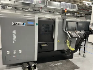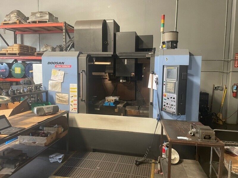
Technical Evaluation Guide: How to Identify a Quality Used, Secondhand, Pre-Owned, Surplus DOOSAN MYNX 5400/50 CNC Vertical Machining Center made in South Korea
1. Benchmark / Reference Specifications — What You Should Expect
Before going on site, get hold of the factory build sheet / specification for the exact serial / variant. Use this as your control. As a reference, here are specs for the MYNX 5400/50 II (or closely related MYNX 5400 family) from Doosan / DN Solutions listings:
| Spec | Typical Value / Range | Source / Notes |
|---|---|---|
| X travel | 1,020 mm | DN Solutions spec for MYNX 5400/50 II lists X = 1020 mm |
| Y travel | 550 mm | Spec sheet: Y = 550 mm |
| Z travel | 530 mm | Spec sheet: Z = 530 mm |
| Table size | 1,200 mm × 540 mm | Many listings for 5400/50 II use 1200 × 540 mm table |
| Max table load / workpiece | ~1,000 kg | Spec says “Max. Table Weight 1000 kg” for MYNX 5400/50 II in some listings |
| Rapid traverse (X / Y / Z) | 30 / 30 / 24 m/min | Spec sheet: X, Y rapid = 30 m/min ; Z = 24 m/min |
| Spindle speed | 8,000 rpm (for many 5400/50 units) | Many machines list 8,000 rpm as top spindle speed |
| Spindle power / torque | ~15 kW power in many used spec sheets | DOOSAN 5400/50 listing: 15 kW spindle power |
| Tool magazine / tool stations | 24 tools | Many spec sheets list 24 tool stations for MYNX 5400/50 II |
| Taper / tool interface | BT-50 / ISO 50 (often “Big Plus” style) | In the spec for 5400/50 II: BT 50 Big Plus taper used |
These numbers should act as guide rails. If the machine you’re inspecting falls far outside, you must ask: is it a variant (e.g. lower spindle, older model), or has something been changed or removed?
Also note that the MYNX series is designed for heavy-duty vertical machining, box-type guideways, high rigidity, and relatively large envelopes.
2. Documentation & History Review (Before / At Start)
Collect as much documentary evidence as possible. The better the records, the lower your risk.
- Factory build sheet / configuration drawing: confirms what options, spindle type, tool changer, axis lengths, drive systems were installed originally.
- Maintenance / service logs: complete, dated entries for preventive maintenance (lubrication, spindle rebuilds, axis checks, alignment).
- Operating hours & utilization: total runtime, load hours vs idle / traverse, shifts, duty cycles.
- Repair / modification history: any crashes, repairs, part replacements (especially spindles, axes, tool changer, wiring).
- Calibration / alignment / metrology reports: earlier tests of straightness, backlash, spindle runout, repeatability.
- Tooling / accessory list: what comes with the machine (holders, fixtures, probes, extra tooling).
- Electrical / control backups, parameter archives, alarm logs: ability to restore parameters, review fault history.
- Spare parts / consumables used: whether OEM parts were used or substituted.
If the seller can’t supply credible history, treat it as higher risk and demand stricter acceptance testing and warranties.
3. Visual / Structural / Cold Inspection (Machine Powered Off)
With the machine safe and unpowered, do a careful external inspection of structure, covers, and visible subsystems.
Structure, Frame & Base
- Inspect the base, column, casting joints, cross-braces, and support frames for cracks, weld repairs, deformations, misalignment.
- Look for surface corrosion, pitting, rust especially in hidden or moisture-prone zones (corners, underside).
- Check whether covers, panels, guards, splash shields, wipers and bellows are present and undamaged. Missing covers often let chips / coolant ingress, accelerating wear.
- Inspect fasteners and bolted joints: none should be loose, missing, deformed, or mismatched.
Guideways / Linear Surfaces & Slides
- Examine exposed guideway surfaces (X, Y, Z) for scoring, scratches, pitting, chipped edges, uneven wear.
- Check protective seals, wipers, covers for integrity; damaged or missing covers is a red sign.
- Look at slideway edges, bearing surfaces, lubricant swash or groove areas: signs of contamination or abrasion.
Spindle Housing / Spindle Nose / Taper Interface
- Inspect the spindle nose / taper seating surface for pitting, corrosion, dents, discoloration, abnormal wear.
- Examine the housing, bearing cover surfaces, seals, cooling passages for leaks or damage.
- Check for signs of heat discoloration or repair marks.
Tool Changer / Magazine / Arms
- Inspect the tool magazine carousel, rails, arms, grippers, indexing surfaces. Look for wear, damage, looseness, broken components.
- Watch for cracked pockets, worn rails, sensor housings, misalignment of tool arms.
Wiring, Electrical Cabinets, Panels
- Open panels and inspect wiring, power modules, circuit boards: check insulation, corrosion, heat marks, splices.
- Inspect cable carriers and conduit: look for chafing, broken loops, slack, broken clamps.
- Check coolant hoses, hydraulic lines, pneumatic lines for leaks, damage or aging.
Coolant / Lubrication / Chip Handling
- Inspect coolant pump, coolant piping, nozzles, filters, hoses for leaks, corrosion, sediment, deterioration.
- Check lubrication distribution piping/lines for each axis: ensure lines intact, no leaks or blockages.
- Examine chip conveyor / evacuation path: belts, screw conveyors, chip trays, guides.
If any structural cracks, heavy external damage, missing critical covers, or signs of neglect exist, these are immediate red flags (though not necessarily deal-breakers if repairable and accounted for).
4. Mechanical / Kinematic / Static Checks (Manual / Low-Speed Moves)
If the machine allows manual jogging or incremental movement, test mechanical behavior, backlash, binding, and smoothness.
Axis Movement – X, Y, Z
- Jog each axis slowly through portions of travel. Feel for binding spots, “gritty” feeling, resistance changes, jumps.
- Reverse direction and measure backlash / hysteresis using a dial indicator (move +X then –X, see lag). The backlash should be minimal and uniform.
- At several positions, mount a test indicator and check straightness / deviation of motion along the travel.
Toolholder / Spindle Static Play
- Mount a precision toolholder or test bar (well cleaned and seated). Gently tap or twist to detect radial or axial play (should be none or minimal).
- Use a dial indicator to measure runout at the tip / taper face.
- Use a marking / dye contact test: apply a thin film to taper seating surface, seat the toolholder lightly, rotate slightly, remove and inspect contact patch. Uniform contact is ideal; partial contact is a warning of wear / misalignment.
Tool Changer / Magazine Static Checks
- Manually index the tool changer (if allowed) through several positions; observe whether indexing is smooth, no hesitation or misalignment.
- Check gripper action, pocket alignment, sensor limit switch behavior.
Drive / Couplings / Gearbox Movement (Static)
- If safe and accessible, gently turn or jog drive shafts or couplings by hand (or in low-power jog) to sense binding, detents, stiffness, irregular motion, or rough spots.
Load / Weight Effects (if possible)
- With a light dummy workpiece or weight in place, see whether carriage sag or deflection under static load is evident or variable.
If you detect binding, excessive backlash, play in toolholders, or irregular motion in static tests, these need deeper analysis or should be factored into pricing.
5. Power-On / Dynamic / Functional Testing
Once safe power conditions exist, test dynamic behavior under motion and, ideally, with light machining.
Control / CNC Interface & Initialization
- Power on the CNC. Observe initialization, alarm / error logs, axis enable states, parameter loading.
- Test operator interface: jogging, incremental moves, overrides, manual / auto modes.
- Perform homing / reference cycles for all axes and confirm consistent referencing.
- Run a “dry run” or motion-only G-code program (no cutting) combining axes to check for smooth transitions, axis interference, stalls, collisions.
Axis Motion & Accuracy
- Execute “box moves,” ladder / rectangular patterns (X then Y then Z) while measuring (via external indicators or in-built diagnostics) deviation, repeatability, straightness.
- Do return-to-zero cycles and measure deviations.
- Monitor axis acceleration / deceleration for overshoot, jerk, instability, motion oscillation.
Spindle Ramp / Behavior
- Ramp spindle from low rpm to full rated rpm (e.g. up to 8,000 rpm or machine’s top) and listen/feel for bearing noise, vibration, smoothness.
- Monitor spindle motor current draw, temperature, whether it holds rpm under small load.
Light Machining / Test Cuts (if feasible)
- Mount a soft material (e.g. aluminum block) and perform a light milling pass, facing or contour pass. Observe surface finish, chatter, feed consistency, stability.
- Check dimensional result vs programmed values.
- If machine has high-pressure coolant or through-spindle coolant, test it while cutting.
- Monitor how cutting affects vibration, current, axis response.
Tool Change / Magazine Cycle Test
- Execute full tool change cycles via CNC: magazine index, gripper arm motion, tool pick / place, etc. Watch for hesitation, misloads, tool drops, collisions.
- After multiple tool changes, re-check tool offsets / lengths for drift.
- Test whether tool change is fast, repeatable, and safe.
Warm-up / Thermal Drift Test
- Run the machine with spindle motion (even idle) for 30–60 minutes or more. Then re-check reference positions, test cuts, repeatability to detect geometry drift due to temperature.
- Monitor servo motor / axis temperatures and check if temperature gradients emerge and correlate to shift in geometry.
6. Metrology / Precision & Accuracy Validation
This is critical to determine whether the machine is “fit for purpose” in your precision or production tolerances.
- Linearity / straightness: over full travel of X, Y, Z axes, measure deviation from ideal straight line using gauge, laser interferometer or similar.
- Orthogonality / squareness: check whether axes are perpendicular (X–Y, X–Z, Y–Z) within acceptable tolerances.
- Backlash / hysteresis quantification: through small forward / reverse offsets and measuring reversal error.
- Spindle / tool tip runout: mount a precision test bar and measure radial and axial runout of the spindle / tool holder.
- Tool change repeatability: after tool change, measure the tool tip offset position and check variation.
- Thermal repeatability test: compare measurements before and after warm-up to see drift.
- Cutting accuracy test: produce a test workpiece with known dimensions and measure deviation from programmed values.
- Surface finish / chatter / vibration analysis: check machined surfaces for irregularities, waviness, chatter marks.
Compare your measured deviations with factory tolerances (if available) or with the tolerances required in your production context. Minor deviations may be acceptable; large or inconsistent ones are red flags.
7. Red Flags & Warning Signs
Throughout inspection and testing, watch for these warning signs — encountering many of them should lower your willingness to accept without deep discount or repair guarantee:
- Large or inconsistent backlash in linear axes or toolchanger
- Binding / sticky zones in axis motion
- Spindle bearing noise, vibration, or detectable play (static or at speed)
- Uneven taper contact or poor dye test for toolholder seating
- Tool change failures, misindex, tool drop, collisions
- Thermal drift that shifts geometry significantly
- Poor repeatability or deviation on return moves
- Missing / damaged covers, wipers, bellows (allow contamination)
- Structural repairs, welds, casting damage in key areas
- Control / CNC error logs, parameter corruption, axis disable faults
- Overheated motors or drive modules, abnormal current draw
- Poor or absent maintenance / calibration history
- Obsolete or unsupported parts / control electronics
If you see multiple red flags, you should demand heavy discounts, require seller repairs, or consider walking away.
8. Refurbishment / Risk Buffer & Cost Estimate
Even a well-maintained used machine often requires refresh work. In your budget / offer include:
- Spindle bearing replacement or spindle overhaul
- Re-scrape / refurbish guideways, rails, slide surfaces
- Replace or repack ballscrews, nuts, encoders
- Tool changer / magazine overhaul or repair
- Control / servo / drive electronics refurbishment or replacement
- Re-lubrication, coolant / fluid system cleaning, piping replacement
- Cover / bellows / wiper replacement, cable carriers, wiring repair
- Calibration, alignment, metrology validation, test cuts after installation
- Rigging, leveling, installation at your site
- Contingency buffer (10–20 % or more) for hidden issues
9. Contract / Acceptance Safeguards & Test Protocols
To protect your investment, include the following in your purchase / acceptance agreement:
- On-site / acceptance test period: machine must be run (motion + spindle + tool change + test cuts) under your conditions (or simulation) for a defined time before final acceptance.
- Acceptance criteria / tolerance sheet: define acceptable limits for backlash, runout, repeatability, drift, test cut accuracy.
- Sample workpiece / test cut run: bring your representative part or material and have the seller produce it so you can measure and confirm.
- Independent inspection clause: allow you to bring a metrology / machine-tool specialist to validate condition and accuracy before final payment.
- Warranty / guarantee clause: for critical subsystems (spindle, axes, toolchanger) for a short period after acceptance.
- Holdback / payment retention: retain a portion of payment until the machine meets acceptance criteria.
- Disclosure obligation: seller must declare known repairs, wear conditions, modifications, or performance limitations.