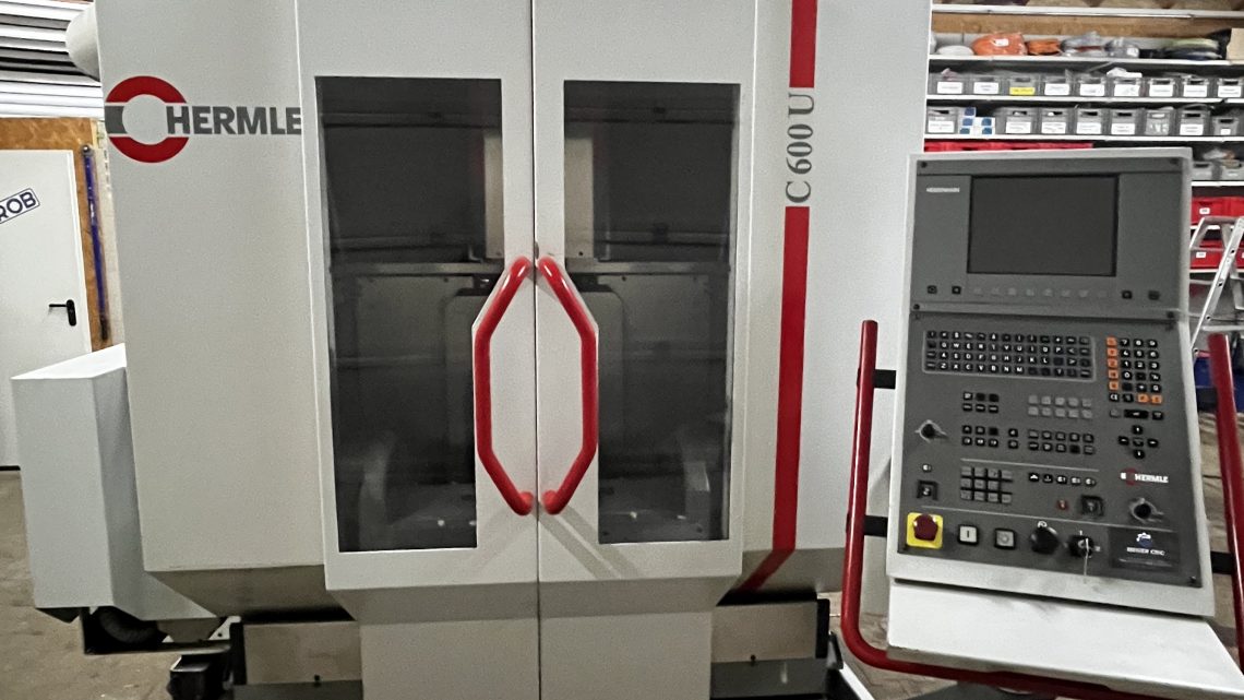
Technical Evaluation Guide: How to Identify a Quality Used, Secondhand, Pre-Owned, Surplus Hermle C600 U CNC Vertical Machining Center made in Germany
Typical Specifications & Baseline Expectations
Before arriving at site, get (or ask the seller for) the factory build sheet / as-delivered specification for that specific unit (serial, options, control, axes). Use that as your benchmark. Meanwhile, here are published spec ranges and features for the Hermle C600 U to help you spot deviations or omissions:
| Spec | Typical Value / Range | Sources / Notes |
|---|---|---|
| X travel (longitudinal) | 600 mm | listing for Hermle C600 U: X = 600 mm |
| Y travel (cross) | 450 mm | Same listing: Y = 450 mm |
| Z travel (vertical) | 450 mm | Many listings show Z = 450 mm (e.g. Hermle spec) |
| Spindle taper / interface | HSK 63 (or HSK 40 variants) | Hermle spec indicates “HSK 63” for C 600 U version in one listing |
| Spindle speed | Up to ~ 15,000 rpm | In one PDF spec, “spindle speed up to 15,000 rpm” for a C 600 U listing |
| Rapid traverse (feed) | ~ 35 m/min (on axes) | The Hermle spec sheet lists “rapid feed = 35 m/min” |
| Tool magazine / ATC | 30 positions | Many used listings show 30 tool positions for C600U |
| Rotary / Swivel Table | Table Ø 280 mm, swivel ± range (A) | The listing shows “swivel rotary table diameter 280 mm … swiveling range A-axis +20 / –90°” |
| Workpiece / table load | ~200 kg | Used listing: “Table load max. 200 kg” under Hermle C600U spec |
These specs help you recognize when a machine is severely underspecified or modified. For instance, if a machine being sold as “C600 U” has only 8,000 rpm or only 20 tool positions, that should raise a flag (unless documented as a lower variant or stripped unit).
Inspection / Evaluation Workflow & Checks
Below is a phased checklist of what you or your technical inspection team should verify (in order). Use the based spec sheet as your benchmark.
1. Documentation & History Review (Before or at arrival)
- Request the original build / delivery / configuration drawing / spec sheet for that serial number.
- Request maintenance logs / service history: spindle rebuilds, calibration, axis alignment reports, component replacements.
- Ask for operating hours (spindle hours, axis motion hours).
- Ask for repair / modification history: any crashes, part swaps, structural repairs or retrofits.
- Check for metrology / calibration test reports: e.g. ballbar runs, straightness, backlash, repeatability, rotary table calibration.
- Inventory of tooling / fixtures / spare parts included.
- Control / CNC backups, parameter archives, error / alarm logs.
- Electrical wiring / circuit diagrams, spare boards, control manuals.
If the seller cannot provide solid documentation, you must increase scrutiny in all subsequent tests.
2. Cold / Static Visual & Structural Inspection
With power off, inspect all visible structure, covers, components, interfaces.
- Frame, base, column, castings: look for cracks, weld repairs, distortions, warpage, misalignment, surface corrosion / pitting.
- Guideways, slide surfaces on X/Y/Z: inspect for scratches, scoring, wear bands, pitting.
- Protective elements: check bellows, wipers, covers, seals — if damaged or missing, the internals may have been contaminated.
- Spindle nose / taper: check for pitting, dents, wear, discoloration.
- Spindle housing / bearings area: visually inspect for oil stains, leaks, damage.
- Tool magazine / ATC mechanism: check rails, arms, grippers, indexing cams, pockets for wear, looseness, damage.
- Rotary / swivel table (if present): examine table surface, bearings, pivot joints, rotary drive couplings.
- Wiring, cable carriers, electrical panels: look for damaged insulation, loose or spliced wires, heat discoloration.
- Coolant / lubrication piping, hoses, valves: inspect for leaks, corrosion.
- Chip handling / coolant sump / chip conveyor: check for damage, corrosion, misalignment.
If you see severe structural damage, missing covers, or signs of rough use, that’s an immediate red flag.
3. Mechanical / Kinematic / Static Tests (Manual / Jog)
Where possible, in manual or safe jog mode, test axes to feel mechanical integrity.
- Jog each axis (X, Y, Z) slowly: feel for binding, gritty spots, resistance changes, dead zones.
- Reverse direction and measure backlash with a dial indicator (move +x then –x and detect lag) — should be small and consistent.
- At multiple positions, mount an indicator and check straightness / deviation from linear path.
- Actuate tool magazine / ATC in manual or slow mode: index a few stations, check smoothness, any hesitation or mis-alignment.
- Mount a precision test toolholder / bar (if possible). Gently twist or tap to detect axial or radial play.
- Use a dial indicator to measure runout at the tool tip or taper.
- Perform a dye / marking compound test on the taper seating surface (coat lightly, seat tool, rotate slightly, remove, inspect contact patch). Uniform contact is desired.
Significant backlash, binding, or toolholder play is a serious warning.
4. Power-On / Dynamic / Functional Testing
Assuming safety, power up and test dynamic / motion / spindle functions.
- Power on the CNC / control: observe startup, error / alarm logs, parameter initialization.
- Test the operator interface: jogging, MDI commands, override, manual modes.
- Perform homing / referencing cycles on all axes, ensure axes reference reliably.
- Run motion-only test program: a path combining X/Y/Z moves (no cutting) to test smooth transitions, axis synchronization, collisions, stall points.
- Test spindle: ramp spindle from low rpm up to rated rpm, monitor sound, vibration, bearing noise.
- Perform a light machining / milling / drilling pass on a soft material (aluminum or equivalent) to test actual cutting performance: check surface finish, chatter, load consistency.
- Execute tool change cycles via CNC: check speed, accuracy, mis-loads, gripper behavior.
- If there is a rotary / swivel table, cycle it under load programmatically: check smooth motion, indexing accuracy, torque consistency.
- Warm-up / thermal drift test: run the machine for 30–60 min, then re-check zero positions, test moves or small cuts to detect drift.
During dynamic tests, monitor servo currents, vibrations, thermal changes, axis stability.
5. Metrology / Accuracy & Precision Verification
To certify that the machine is precise and capable, perform measurement tests (using gauges, indicators, laser tools, etc.).
- Straightness / linearity of each axis (X, Y, Z): over full travel, measure deviation vs ideal line.
- Orthogonality / squareness: between axes (X–Y, X–Z, Y–Z) test perpendicularity.
- Backlash / reversal error in axes: small offset moves and measure return error.
- Toolholder / spindle runout: mount test bar and measure radial & axial deviation.
- Tool change repeatability: after several tool changes, measure tool tip offsets to see drift.
- Thermal drift / repeatability: compare measurements before and after warm-up.
- Test cut accuracy: machine a known test geometry and measure dimensional deviation from program.
- Surface finish / chatter: inspect finished surfaces under microscope or profilometer for irregularities.
Compare your results to the factory tolerances (if available) or your acceptable production tolerances. Deviations that are too large or irregular may disqualify the machine for precision work.
Red Flags & Warning Indicators
During all phases, these are warning signs you should watch for (and negotiate or reject if they appear):
- Excessive backlash / sloppy axes
- Binding / sticky zones or uneven resistance in motion
- Spindle bearing noise, vibration, or discernible play
- Toolholder taper damage or inability to achieve full contact in dye test
- Tool change problems: misindexing, hesitation, dropped tools
- Rotational / swivel table misalignment, indexing inaccuracy
- Thermal drift too large after warm-up
- Poor repeatability on return-to-zero or test moves
- Structural repairs, welds, casting damage in key load-bearing zones
- Missing or degraded covers / bellows / protective seals (leading to contamination)
- Control / CNC error logs, instability, parameter corruption
- Overheated motors, drive issues, servo faults
- Lack of credible maintenance history / missing critical spare parts
- Obsolete or unsupported control modules, electronics
If you see multiple red flags, you must demand deep discounts, repairs, or walk away.
Contract / Acceptance Safeguards & Test Protocol
To protect your investment, build in the following contractual and procedural safeguards:
- On-site / acceptance test period: require full operational demonstration (motion, spindle, tool change, test cuts) before final acceptance.
- Acceptance tolerance sheet: define allowable ranges for backlash, runout, repeatability, drift, test cut error.
- Test part / sample run: bring representative workpiece or geometry and require the seller to machine it for your measurement.
- Independent inspection clause: permit you to engage a metrology / machine-tool expert to verify before final payment.
- Warranty / guarantee (for critical systems): e.g. spindle, axes, toolchanger, for a defined period after acceptance.
- Retention / holdback clause: withhold a portion of payment until the machine meets acceptance criteria.
- Disclosure requirement: seller must fully disclose known repairs, wear, modifications, or performance limitations.