Technical Evaluation Guide: How to Identify a Quality Used, Secondhand, Pre-Owned, Surplus JD Squared RC-6 Rotary Plasma Tube & Pipe Cutter made in USA
Known Specifications & Baseline Expectations (JD2 RC-6)
First, here are key published specs / features of the RC-6 from JD Squared, which you should use as your reference baseline:
- The RC-6 is a rotary plasma tube & pipe cutter by JD Squared.
- Max outside diameter (with tube stabilizer): 6″ schedule 40 pipe, 4″ square tubing, 4″ channel, 4″ angle iron.
- Max outside diameter (without stabilizer) (reduced length): 8″ schedule 40 pipe, 6″ square tubing, 5″ channel / angle.
- Max cutting dimensions (for 12′ machine): Y-axis 10.5′, X-axis 12.5″, Z-axis 7″.
- Max cutting dimensions (for 24′ machine): Y-axis 22.5′, X-axis 12.5″, Z-axis 7″.
- Motors: brushless servo motors on all axes.
- Power / supply: 190–240 VAC, 1 phase with neutral, 50/60 Hz, 30 A (machine only). With optional router control, 40 A.
- Construction claim: JD Squared advertises “US manufacturer … made in the USA.”
Use these specs to detect anomalies: if the machine you inspect has lower cuts, missing axes, degraded torque, or modified travel, those are warning signs.
1. Documentation & History Review
Before touching the machine, collect all documentation you can. The more history you have, the more confident your assessment.
Essential Documents to Request / Examine:
- Original build sheet / serial / configuration documentation: which version (12′ or 24′), which options (rotary stabilizer, router option, extension kits).
- Maintenance / service logs: hours, lubrications, axis servicing, torque tests, alignment checks.
- Plasma power supply / torch logs: hours on the plasma unit, torch replacement, consumables used.
- Modifications / repairs: whether axes, rails, servo drives, motion parts, or structure have been repaired or replaced.
- Cut records / sample parts: do you have sample cut pipes / tubes to inspect?
- Control / software backups, parameter files, motion profiles, error logs.
- Wiring / electronics schematics, motor nameplates, drive specs.
If the seller cannot produce credible documentation, you should greatly increase the time you spend on hands-on inspection and insist on stronger guarantees.
2. Visual / Structural / Cold Inspection
With the machine powered off, do a careful walk-around and inspect all visible structure, motion mechanisms, and interfaces.
Structure, Frame & Base
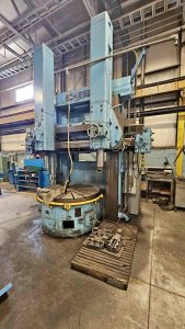
- Inspect the base, rails, gantry, cross beams, frame welds, joints, supports for cracks, repairs, distortions, sag. The RC-6 is expected to be rigid enough to maintain positional accuracy over long cuts.
- Check for corrosion, pitting, rust—especially in parts exposed to moisture, splatter, or chips.
- Verify all protective covers, guards, chip shields, cable covers, bellows or conduits are present and intact. A missing cover is a potential entry point for damage.
- Inspect mounting and leveling points: holes, shims, structural pads for wear or deformation.
Rails, Guides, Linear Motion Parts
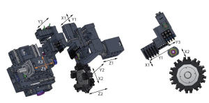
- Look along X, Y, Z linear rails / linear ways or guides for scoring, scratch marks, pitting, wear tracks.
- Examine wipers, scrapers, bellows: if damaged or missing, debris may have invaded internal slides.
- Inspect guide rail ends and transitions (junctions, corners) where wear is typically heavier.
Rotary / Chuck / Stabilizer Assemblies
- Inspect the rotary axis (rotary chuck or drive) for backlash, wear in bearings, chuck jaw integrity.
- If a tube stabilizer is used, examine its clamping surfaces, jaws, and alignment mechanism.
- Check the interface between the tube and stabilizer: wear, misalignment, chatter marks.
Plasma Torch / Mount / Z-Axis / Gantry Interface
- Inspect torch mount assembly: torch holder, gas feed lines, water lines (if present), wiring insulation, shielding.
- Examine slide surfaces or carriage for Z-axis (vertical motion) for wear, binding, scoring.
- Check tilt or swivel axes (if present) for play, misalignment, wobble in pivot joints.
Electrical / Wiring / Control Cabinets
- Open control / electronics enclosures: wiring insulation condition, no burned or spliced wires, clean connector joints.
- Inspect cable carriers, conduit routing, motors cables, hose runs.
- Check PLC / motion control boards, motor drives for signs of overheating, corrosion, blown components.
Plumbing, Air, Gas & Utility Interfaces
- Inspect gas supply lines (plasma gas, shielding gas), hoses, fittings, valves for leaks, corrosion, damage.
- If water-cooling or coolant injection is used, inspect water lines, connectors, seals, possible leaks.
- Inspect pneumatic lines (if used for clamp / stabilizer) for cracks, leaks, worn tubing.
3. Mechanical / Kinematic / Static Checks
Assuming safe access and the machine allows manual or jog motion, test mechanical behavior, backlash, smoothness, play.
Axis Jog Tests / Linear Motion
- Jog X / Y / Z axes slowly: feel for binding, gritty spots, uneven resistance, “dead zones.”
- Reverse direction and test backlash / lost motion using a dial indicator: command ± small increment and reverse, note the lag.
- At multiple positions along the axis, mount a dial indicator and compare actual motion to ideal (check straightness, flatness).
- See whether motion is consistent across the travel (no stiff / soft zones).
Rotary / Chuck Play / Backlash
- Rotate the chuck or rotary axis manually (if possible) and feel for backlash, smoothness, sticking points.
- Reverse direction and note any slack or lag.
- Attempt light radial / axial push on the chuck (if safe) to detect looseness in bearings or drive.
Torch / Z-Axis / Vertical Motion
- Jog Z-axis up / down. Watch for binding, erratic motion, uneven resistance.
- Reverse direction to test backlash.
- If tilt or swivel axis is present, jog it and sense play or misalignment.
Chuck / Stabilizer Static Checks
- Insert a tube / pipe and check whether stabilizer or chuck clamps concentric without wobble.
- Try small hand rotation / shifting to see whether the shaft is held firmly or allowed play.
Drive / Coupling / Gearbox Check
- If parts of the drive chain (gears, couplings) are exposed, manually rotate or slightly jog drive shafts to feel for rough spots, binding, detents, looseness.
- Look for wobble in couplings, uneven vibration.
4. Power-On / Dynamic / Functional Testing
Once safety checks are satisfied, power up the machine and perform dynamic and operational tests. Always proceed carefully.
Control / CNC & Initialization
- Power on the CNC / motion controller. Observe boot sequence, alarm / error messages, parameter loads.
- Test manual jogging / incremental moves via control interface.
- Home all axes / reference sequences and check consistency.
- Test coordinate system display, position readouts, motion limits, overrides.
Axis Motion Under Power
- Run motion-only (no plasma) programs with combined X / Y / Z motions. Observe smoothness, no stalling, no abrupt jerks.
- Execute return-to-zero movements, repeated reference moves to test repeatability.
- Observe acceleration / deceleration behavior; avoid overshoot or instability.
Plasma Torch Activation (No Cut) / Simulated Cut
- If possible, activate plasma torch (without actual cutting) to test torch on/off control, arc start / stop commands, gas flow, ignition behavior (if safe).
- Monitor torch wiring, gas lines, control signals, arc stability, whether the controller coordinates torch activation with motion.
Cutting / Test Cut Execution
- Run a test cut on a representative tube / pipe / angle (within specification) under controlled parameters.
- Observe plasma arc quality, cut speed, line straightness, width / kerf quality, dross, edge finish.
- Inspect cut edges visually and dimensionally.
- While cutting, monitor motion axes for vibration, instability, or lag.
- Retrace / repeated cuts to test multi-pass consistency.
Rotary / Chuck / Stabilizer Dynamics
- During cut, observe stability of rotary chuck, any vibration or runout, whether the stabilizer holds the tube firmly without chatter.
- Command various rotation speeds and transitions and monitor smoothness during direction changes.
Warm-Up / Thermal Drift Test
- Run system (motion + torch idle or light cut) for ~30–60 minutes. Then repeat reference moves / test cuts to detect any drift in geometry or alignment.
- Monitor motor, drive, torch / gas components, axes for temperature rise and resulting performance shifts.
5. Metrology, Accuracy & Performance Verification
To confirm the machine is suitable for your production tolerances, perform measurement and evaluation tests.
- Straightness / linearity: check deviations in X / Y / Z axes vs ideal line across the travel.
- Squareness / orthogonality: verify axes are perpendicular within tolerance.
- Backlash / reversal error: quantify hysteresis in axes.
- Rotary runout / chuck concentricity: mount a precision test bar or tube and measure radial / axial deviation during rotation.
- Tool change / torch mounting repeatability: after multiple cycles of torch indexing or pistol repositioning, measure positional consistency.
- Cut accuracy: produce a cut geometry with known dimensions; measure deviation of cut line from the motion program.
- Edge / finish quality: examine cut edges (kerf width, bevel, dross, taper) to assess quality.
- Repeatability / multi-pass consistency: repeated cuts should align well; drift across passes should be minimal.
- Thermal drift: measure before and after warm-up and compare geometry.
6. Red Flags & Warning Signs
During inspection and testing, watch for these warning signals. Multiple occurrences suggest serious issues you must demand fixes or reject the unit.
- Excessive backlash or motion slop, inconsistent across axes.
- Binding or sticky zones in axis motion.
- Rotary or chuck bearing noise, vibration, play under load.
- Plasma torch ignition / arc stability problems (misfires, drift).
- Cut quality severely compromised (excessive dross, kerf wander, bevel, misalignment).
- Motion lag or servo instability during cutting.
- Thermal drift so large that geometry shifts significantly.
- Stabilizer / chuck misalignment, looseness, inability to clamp concentric.
- Structural repairs or welds in frame, base, rails.
- Damaged, missing, or degraded covers, wipers, shields (leading to contamination).
- Control / CNC errors, memory corruption, axis disable faults.
- Overheated motors or drive modules, current irregularities.
- Missing or corroded wiring, gas line damage, torch wiring insulation failure.
If you see several red flags, renegotiate heavily, require repairs, or consider rejecting the unit altogether.
7. Risk Buffer / Refurbishment Estimate
Even a well-maintained RC-6 may require servicing. Budget for:
- Servo motor / drive replacement or repair
- Linear rail / guide refurbishing or replacement
- Rotary chuck / bearing replacement or reconditioning
- Torch / torch mount, gas lines, water lines refurbishment
- Control / electronics refresh, wiring harness repair
- Calibration, alignment, metrology verification, test cut tuning
- Replacement of protective covers, shields, wipers, cable carriers
- Installation, leveling, commissioning at your site
- Contingency buffer (10–20 % or more) for hidden wear or damage
8. Contract / Acceptance Safeguards & Test Protocols
To protect your investment, build in the following contractual clauses and test acceptance requirements:
- On-site / acceptance test period: require the machine to be operated fully (motion + plasma cuts) in your environment before final acceptance.
- Acceptance criteria / tolerance schedule: define allowable deviation in cut geometry, motion repeatability, backlash, runout, drift.
- Test piece / sample cuts: bring representative tubes / shapes and require the seller to produce them so you can measure actual performance.
- Independent inspection clause: allow you to hire a plasma / CNC motion expert to verify condition before final payment.
- Warranty / guarantee (for critical subsystems): e.g. servo motors, torch interface, rotary bearings, for a defined post-commissioning period.
- Holdback / retention clause: withhold a portion of payment until the machine meets acceptance tests.
- Disclosure requirement: seller must document any known defects, repairs, limitations, or replaced parts.