Technical Evaluation Guide: How to Identify a Quality Used, Secondhand, Pre-Owned, Surplus Hwacheon Sirus UM CNC High Speed Mold Vertical Machining Center made in South Korea
1. Baseline Specification & Features (What a “Good SIRIUS-UM” Should Be)
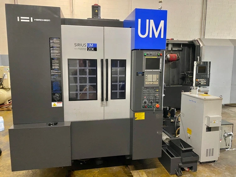
Before inspection, you should obtain the original factory build sheet or specification sheet so you know exactly which spindle, options, and tolerances your candidate machine should have. Below are some typical published specs for the Hwacheon SIRIUS-UM / UM+ machines (for die & mold / high-speed use) that you can use as reference “red lines”:
| Parameter | Typical / Published Value | Notes / Sources |
|---|---|---|
| X / Y / Z travel | ~ 750 / 500 / 450 mm | from Hwacheon specification pages for SIRIUS-UM+ |
| Table size / work surface | ~ 850 × 500 mm | |
| Table loading capacity | ~ 800 kg | |
| Spindle speed (standard / optional) | 20,000 rpm typical; optional 32,000 / 45,000 rpm | Hwacheon lists standard and optional high-speed spindle variants. |
| Spindle motor / power | e.g. ~ 18.5 / 11 kW (for 20,000 rpm version) | in published spec sheet for SIRIUS-UM+ |
| Spindle taper / tool holders | BT-40 / BBT-40 / HSK (depending on variant) | Hwacheon spec lists BT-40 / BBT-40 / HSK variants for SIRIUS-UM+ machines. |
| Rapid traverse / feed rates | ~ 24 m/min in X/Y/Z rapids | Hwacheon spec states rapids of 24 m/min for all axes. |
| Tool changer / magazine | ~ 24 tools standard (optionally 30, 60, etc.) | Spec sheets mention 24 standard, optional expansions. |
| Machine size / footprint / weight | ~ 2,585 × 3,200 mm floor footprint; ~ 8,000 kg weight | Spec sheet gives ~8 tonne weight and floor dimensions. |
| Cooling / thermal control & displacement compensation | Oil-jet cooling, spindle displacement monitoring, frame displacement compensation (Hwacheon systems like HSDC, HFDC) | Published documentation of the SIRIUS series mentions these thermal compensation / cooling systems as built-in features. |
These published specs should act as your “checksheet baseline.” If the machine you inspect deviates significantly (e.g. much lower spindle speed, smaller travel, weak rapid rates, lacking cooling / compensation features) that is a red flag (or at least requires explanation).
Also note that in used / surplus markets, many machines may have had spindle upgrades, retrofit control changes, or option removals, so always compare the machine to what its own build sheet should say, not just the “generic model.”
2. Documentation & History Review
Before or during your site visit, gather all documentation and history you can. A machine with detailed, credible history is lower risk.
- Original build sheet / factory drawing — shows which spindle, cooling, compensation systems, tool changer, options were installed.
- Service / maintenance logs, ideally date-stamped with records of preventive maintenance, alignments, spindle rebuilds, wear measurements, re-scraping, etc.
- Operating / runtime hours — total hours, and if possible separation between idle (movement only) vs heavy cutting hours.
- Repair / modification records — any crash incidents, structural repairs, retrofits, spindle change outs, control / servo / drive replacements.
- Calibration / metrology reports — past laser alignments, ballbar reports, straightness / flatness measurements.
- Backups of CNC parameters, control files, error logs — to see how stable the controller and system have been.
- Spare parts usage / OEM parts record — whether genuine parts were used or cheaper substitutes.
- Spare tooling / accessories / attachments supplied with the machine (e.g. probing systems, fixtures, cooling systems) and their condition.
Reject (or heavily discount) machines with scant or no credible history.
3. Visual & Structural / “Cold” Inspection
With the machine powered off, thoroughly inspect the exterior, structure, and accessibility of key parts.
Frame, Base, Castings, Column, Box Structure
- Look for cracks, weld repairs, distortions in the machine base, column, cross-beam / gantry (if applicable), support frames.
- Inspect for corrosion, pitting, rust especially on exposed surfaces, guide surfaces, bottom of enclosures, behind covers.
- Check whether splash guards, covers, way wipers, bellows, chip guards are intact. Missing or damaged covers often mean internal parts got contaminated by chips / coolant.
- Examine cable tracks, wire conduits, hoses: fraying, kinks, exposed wires, wear marks — these are red flags.
- Look for coolant / oil leaks stains, residue, corrosion marks around pumps, piping, joints, backsplash areas.
Spindle Housing, Head / Z-axis, Quill (if any)
- Inspect the spindle nose / taper area: pitting, oxidation, wear, dents, discoloration.
- If there’s a quill or extension head, check whether it moves smoothly, check for scuffing or wear marks.
- Inspect housing seams, gaskets, cooling jackets, piping, connections for damage or leakage.
Table & Work Surface
- Check table surface for wear, flatness, pitting, scratches, mounting hole damage.
- Inspect T-slots: whether the edges are intact, whether they have been reworked, whether there is rust / corrosion inside the slots.
- Check underside of table and support structure for cracks or deformation.
Tool Changer / Magazine
- Inspect the tool magazine, carousel, rail, selectors for wear, corrosion, broken parts, misalignment.
- Check grasping / gripper arms, index motors, sensors, limit switches for damage or looseness.
Fasteners, Access Panels & Joints
- Examine major fasteners, bolts at structural joints: look for missing or mismatched bolts, signs of rework, torque damage.
- Open access / inspection doors, panels, covers: check hinges, seals, latches.
- Check for signs of tampering or nonstandard modifications.
4. Mechanical / Kinematic Tests (Cold or Slowly Powered)
With the machine off (or safe “jog / manual” mode) but able to move, test mechanical movement, backlash, wear, and basic integrity.
Linear Axes, Guides & Ball Screws
- Jog each axis (X, Y, Z) slowly (manual or low speed) through full travel. Feel for smooth, continuous motion—no gritty spots, jumps, binding, or dead zones.
- Reverse direction at various points and measure backlash using a dial indicator. The measured hysteresis (lost motion) should be within acceptable original tolerances (or small).
- Use test indicators or reference gauges to check straightness, flatness, pitch error over travel length. Note deviations / drift.
- Inspect ball screw shafts: look for wear, pitting, galling, lubrication residue, damage to threads.
- Check ball nut housings for play or looseness. Any wobble is a red flag.
- Examine guide rails / linear guides (roller, linear ways, box ways): check for pitting, scoring, corrosion, uneven wear patterns.
- Confirm lubrication delivery: whether each axis has oil / grease supply, whether lines are intact and show evidence of lubrication (not dry).
Spindle / Taper / Bearing Checks (Cold)
- Mount a good, clean, precision toolholder or test bar. Gently rotate (if possible) or twist and check for axial / radial play. It should be minimal or near zero.
- Use a dial indicator to measure runout at the tool tip or taper face.
- Do a “spot / dye” contact test: apply machinist’s dye (Prussian blue or other marking compound) lightly to the spindle taper and seat the toolholder, rotate slightly, remove, inspect contact pattern — it should be uniform (no partial / uneven contact).
- Check the drawbar / tool retention mechanism: whether it moves freely, without slop, binding, or inconsistencies.
Tool Change & Magazine Mechanism
- Cycle the tool changer manually or in slow automatic index mode through all positions. Listen/feel for hesitation, binding, misindex, dropped stations.
- Test gripper arms, locking mechanisms, sensors, limit switches for proper operation and repeatability in manual mode.
Auxiliary Systems (Coolant, Chip Handling, Hydraulics / Pneumatics)
- Inspect coolant pump, pipes, nozzles, filters, sumps. Check for sludge, corrosion, leaks.
- Test chip conveyor / chip removal (if present) by hand: belts, screws, augers should move smoothly.
- Inspect hydraulic / pneumatic systems (if installed): hoses, cylinders, valves, pressure lines. Look for leakage, hose degradation, broken fittings.
- Check automated lubrication systems (if any): verify delivery to each axis, check for clogged or dead lines.
5. Power-On / Dynamic / Functional Tests
With proper safety precautions, power the machine and perform operational tests under movement and load.
CNC / Control System
- Power up the control: monitor alarms, fault logs, error history, parameter integrity.
- Test operator panel keys, overrides, MPG (manual pulse generator), jog / MDI / program execution modes.
- Perform homing cycles, reference moves, zeroing, offsets, macro / canned cycles, probing (if installed).
- Run a simple motion program (no load) with combinational axis moves to test smoothness, reaction, stalling, limits.
- Verify all limit switches, safety interlocks, door sensors, emergency stop operations.
Axis / Motion Behavior Under Load
- Run “box motion” cycles and ladder / grid patterns while measuring with a test indicator or laser to check repeatability, accuracy, return-to-zero behavior.
- Test acceleration / deceleration behavior: watch for overshoot, stalling, abrupt jerks.
- Under light cutting conditions (e.g. soft aluminum), run a test program and listen / watch for vibration, chatter, power dips.
- Monitor whether machine holds programmed rates, whether servo tuning is stable.
Spindle Performance Under Use
- Ramp the spindle up through its RPM range (e.g. up to 20,000 rpm) and listen / feel for bearing noise, vibration, swirling, growl.
- Monitor spindle housing / bearing area temperature over a moderate run time (e.g. 15–30 minutes).
- Under light to moderate cutting load, perform a test cut and observe if the spindle holds rpm, if torque drops, if chatter or anomalies emerge.
Tool Change / Cycle Testing
- Execute full automatic tool change cycles via CNC program: observe speed, smoothness, any misloads, indexing errors.
- After multiple tool changes, check whether tool length / offset readings remain stable (i.e. minimal drift).
6. Metrology / Geometric / Alignment Verification
To assess how well the machine still holds geometry, use precision measuring tools (laser interferometer, ballbar testers, granite squares / surface plates, autocollimators):
- Straightness of each axis over full travel.
- Squareness / perpendicularity: e.g. between X & Y, X & Z, Y & Z axes.
- Pitch, yaw, roll deviations, linear deviation / linearity error, pitch error.
- Table flatness, parallelism of table to axes.
- Spindle axis alignment to table (i.e. is the spindle perpendicular or within tolerance).
- For high-speed machines, check thermal drift / displacement under prolonged operation.
- Compare measured values to specification tolerances. Accept small deviations, but large or erratic deviations are red flags.
7. Red Flags & Warning Signs to Watch For
While inspecting, be alert to these common warning signs — any of them should require deep questioning, discounting, or walking away:
- Excessive backlash or slop in axes or spindle that cannot be remedied by adjustment.
- Severe scoring, pitting, gouging, corrosion on guideways, ball screws, ways.
- Spindle bearing noise, vibration, wobble, irregular runout — indicates worn or failing bearings.
- Uneven or partial taper contact (bad dye contact test), damage to spindle nose, burn marks.
- Tool changer misindexing, hesitation, tool-drop issues in some slots.
- Frequent or unexplained control / CNC errors, memory faults, parameter issues.
- Severe thermal drift (geometry shifting substantially during warm-up).
- Missing or damaged covers, torn way wipers or bellows (leading to contamination).
- Evidences of crash / structural impact repairs, welds, distorted frames, replaced castings.
- Non-OEM retrofits or undocumented modifications that might impair original design or rigidity.
- Lack of maintenance history / inconsistent logs.
- Obsolete / hard-to-find spares or control parts (especially for high-speed spindle parts).
- Drift in tool offsets after tool changes (i.e. tool change repeatability problems).
If you see multiple of these, the machine is risky unless very well discounted and with repair allowances.
8. Repair / Refurbishment Cost Estimation & Risk Buffer
Even a “good” used SIRIUS-UM probably needs some refresh. Before purchase, budget for:
- Spindle bearing replacement or full spindle rebuild (especially for high-speed spindle).
- Re-grinding or replacement of ball screws / nuts.
- Re-scraping / honing / re-lapping guideways or slide surfaces.
- Overhaul / reconditioning of the tool changer / magazine / grippers.
- Replacement or repair of covers, wipers, bellows, cable carriers.
- Control / servo / drive electronics refurbishment or replacement.
- Full alignment, calibration, laser metrology, certification after installation.
- Shipping, rigging, foundations, installation at your site.
Allow a safety margin (e.g. 10–20 % extra) for unexpected wear or hidden issues.
9. Acceptance Tests, Warranty & Purchase Safeguards
To protect your investment, include the following in your purchase negotiation:
- On-site test run / “burn-in” period (e.g. 8–24 hours of light production) after delivery to your facility, during which the seller must correct latent defects.
- Acceptance criteria documented in the contract (tolerances for backlash, runout, positioning, repeatability, test cut results).
- Test cut / sample part run using your measuring tools to verify performance.
- Limited warranty / guarantee on critical components (spindle, tool changer, drive systems) for a defined period post-acceptance.
- Optionally hire a third-party machine inspection / metrology firm to verify performance independently before final payment.