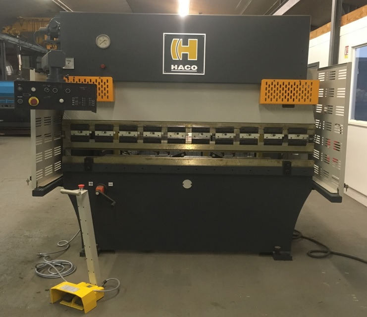
Technical Evaluation Guide: How to Identify a Quality Used, Secondhand, Pre-Owned, Surplus Haco PPH2040 Press Brake made in Belgium
Preliminary Info & Typical Specs (So You Know What to Expect)
Before the inspection, collect as many original specs / machine documents as you can (from seller or factory). Use those as your “control chart” to spot serious deviations. For Haco PPH2040, some available data from used-machine ads:
- Model: PPH2040 (sometimes seen as PHH2040, or variant)
- Bending / pressing force: 40 tons (~ 400 kN) according to listings (e.g. “Pressing force: 40 t”)
- Working / bending length: ~ 2,100 mm (≈ 2100 mm)
- Distance between frames (clearance between uprights): ~ 1,600 mm for some units
- Projection / throat depth: ~ 220 mm (for some PPM2040 listing)
- Stroke / ram travel: some used listing says ~ 100 mm stroke length
- Working height (table to ram): e.g. 880 mm in one listing
- Drive / motor power: ~ 5.5 kW on one listing
- Size / weight: in one listing dimension ~ 2400 × 1400 × 2100 mm, weight ~ 3,750 kg
- Stroke rates / speed: working speed ~ 13 mm/s, retraction ~ 100 mm/s, emptying ~ 70 mm/s in that listing
These “typical” values are your reference. If the machine you’re evaluating departs strongly from these (for example, much less stroke, weak force, extremely slow speeds), that’s a warning — either the machine is downgraded, damaged, or misrepresented.
Also refer to Haco’s maintenance guidance for hydraulic press brakes (they publish general upkeep and maintenance tips)
1. Documentation & History Review
Before going into the shop, gather as much historical and documentation evidence as possible. A well-documented machine greatly lowers your risk. Check for:
- Original factory / build sheet
- Confirms the machine’s original force, stroke, frame width, model options.
- Shows what options / accessories were installed (back-gauge, crowning systems, control type, safety package, etc.).
- Maintenance / service logs
- Regular hydraulic oil changes, filter changes, cylinder rebuilds, seal replacements.
- Dates and hours of maintenance.
- Any overhauls or special repairs (ram regrind, frame straightening, cylinder replacement, etc.).
- Operating hours / utilization
- Total hours of operation (if known).
- If possible, hours under load vs idle. Heavy production use escalates wear.
- Repair / modification records
- Any crash / misbend events, frame repairs / straightening, welding.
- Additions or subtractions (e.g. aftermarket back-gauge, control upgrades, sensor additions) — ensure they’re consistent & documented.
- Past calibration / alignment / inspection reports
- Reports of press alignment, ram parallelism, bed flatness, gauge accuracy, crowning, deflection compensation tests.
- Spare parts, dies, tooling, accessories
- What tooling comes with the machine (upper die, lower die segments, back-gauge fingers, etc.).
- Spare parts inventory (seals, cylinders, hydraulic valves, sensors).
- Electrical / control backups
- Copies of PLC / CNC programs, parameter backups.
- Diagnostic logs, error histories.
If the seller cannot produce credible documentation (or gives vague, contradictory logs), you should reduce your confidence and price accordingly.
2. Visual & Structural / Cold Inspection
With the machine powered off (or made safe), do a full external inspection before moving any parts. Many major problems manifest visibly first.
Frame, Structure, and Machine Bed
- Cracks, welds, repairs, distortions — particularly around the frame, side columns, support beams, ram guides. Check for signs of having been straightened or welded.
- Surface corrosion, rust, pitting — especially in protected areas, in corners, below guards or covers.
- Warping / sagging — look along the bed top and ram for unevenness or signs of bending.
- Missing covers, shielding, guard plates, way wipers — missing protective parts allow chips, debris, and dust ingress, accelerating wear.
Ram & Guide Surfaces
- Inspect the ram faces / guides for wear, scoring, galling, scratches, or deformation.
- Check for parallelism visually (using straight edge, feeler gauges) between ram faces if possible.
- Inspect guide columns or ram support guides (if the press is of guided ram type) for even wear.
Table / Bed / Die Support Surface
- Look at the table / bed surface: is it flat, are there deep gouges, chips, or pitting?
- Examine T-slots (if present), mounting surfaces, holes — check edges for wear, damage, rounding.
- Ensure underside and structural support frames show no cracks or deformations.
Hydraulic Cylinders / Piston Rods / Seals
- Inspect visible cylinder rods: are they straight and free of rust, pitting, scoring?
- Examine seals, gland area for leakage stains, past oil residue or seepage.
- Check for corrosion around connections, hoses, and fittings.
Hydraulic Hoses, Pipes, Fittings, Valves
- Inspect hoses and pipes for abrasions, cracks, bulging, kinking, leaks, old repair tape.
- Check all fittings and joints for corrosion or signs of weeping.
- Look at hydraulic valve blocks / manifolds: any signs of welding, repairs, soldering, or nonstandard modifications.
Back-Gauge & Mechanical Components
- Check back-gauge arms / fingers, rails, linkages, bearings for wear, looseness, misalignment.
- Inspect fingers and stops for deformation, scoring, or misadjustment.
- Inspect guides, rails, rails’ lubricating mechanisms (if any).
Fasteners, Joints, Access Panels
- Check that major bolts, structural connectors are original, intact, properly seated; look for mismatched or missing bolts.
- Open and inspect access panels: hinges, latches, seals.
- Inspect control / electrical enclosures for corrosion, unprofessional wiring, missing covers.
Control / Operator Panel
- Examine keypad, switches, buttons, display panel condition for wear, button fatigue, cracked overlays, signs of heavy usage or replacement.
- Inspect cables, connectors, wiring harnesses entering the panel, ensure no loose or frayed wires.
3. Mechanical / Static Functional Checks (Without Full Power / Controlled Motion)
With the machine safe to move (if possible under slow manual or “jog / inch” mode), test the mechanical behavior of its components.
Ram / Stroke / Movement
- Move the ram (if possible in slow mode) through its stroke; feel for stickiness, binding, uneven force, jerky motion.
- When reversing direction, monitor how smoothly it reverses; any “dead zone” or hesitation indicates friction, wear, or misalignment.
Back-Gauge Motion
- Jog the back-gauge axis (X / Y axes, depth / lateral movement) through full travel. Feel for smoothness, binding, backlash or looseness.
- Reverse direction and measure backlash (looseness) on gauge travel.
Clearance & Synchronization (If Dual Cylinders or Dual Ram Guidance)
- If the machine uses dual cylinders or synchronized ram supports, verify that both sides move together without binding or differential lag.
- Any visible tilt or mismatch in ram motion is a red flag (indicates cylinder mismatch, linkage wear, or frame distortion).
Die / Tooling Fit & Alignment
- Place a known good die set (upper/lower) and check for play in seating / alignment.
- Use feeler gauges to check for uniform contact across die surfaces.
Hydraulic System (Static Checks)
- With machine at rest, check for hydraulic leaks: look at hoses, pipes, cylinder connections, valve seals, tank, return lines.
- Inspect hydraulic fluid clarity in tank (if visible), for contamination, sludge, debris, metal particles.
- Check filter condition (if filters have transparent bowls or visual windows).
- Check return lines for sludge, contaminated oil, milky appearance (water infiltration).
Back-Pressure / Valve Checks
- Without load, manipulate hydraulic control valves (if safe) to see whether ram holds position (no drift) — any drift indicates internal leakage.
- Check adjustment / setting screws on valves, ensure they aren’t tampered or welded.
4. Power-On / Dynamic / Functional Testing
Assuming the machine can be powered and safely tested, run through functional tests to see how it performs under actual conditions.
Control / Electrical System
- Power up the control and observe any alarm / fault messages, diagnostic logs, parameter mismatches.
- Test all operator interface functions: keypad / buttons, jog / inch, manual mode, automatic / CNC bending program mode (if present).
- Test emergency stop buttons and safety circuits, limit switches, interlocks, guarding.
- Run homing / reference cycle for ram and back-gauge axes.
- Test parameter setting, bending programs (if CNC), memory stability, sensor feedback.
Ram / Bending Cycle Test
- Run a simple no-load bending cycle (i.e. move ram down and up) to verify motion, speed, smoothness, absence of jerking or hesitation.
- Monitor for hydraulic anomalies (pressure fluctuations, spiking, sluggish behavior).
- Test at different speeds if possible (slow, medium, fast).
- Use a dial indicator or displacement transducer to measure actual ram travel vs command; check for linearity, deviation, hysteresis.
Back-Gauge & Gauging Test
- Run back-gauge motion simultaneously with ram cycles (if used in program mode): check synchronization, repeatability, positional accuracy.
- Measure stop accuracy: command gauge to a position, use a dial indicator or gauge block to verify position.
- Repeat multiple times to check repeatability.
Bending / Load Test (If Safe)
- If possible, perform a test bend with a mild material (thin sheet) and a known die / tooling.
- Measure the resulting dimension and angle and compare to programmed or expected values.
- Watch for inconsistent bend angles across length, corner deformations, springback anomalies.
- Monitor hydraulic pressure, stability, oil temperature, noise under load, seepage or oil lines.
Drift / Holding Test
- During a static hold (ram held partway down), observe whether it holds position or creeps downward (indicating internal leakage).
- Monitor oil temperature, gauge any pressure drop over time in hold state.
Safety / Protection Systems
- Test over-travel limit switches for ram and gauge axes.
- Verify protective interlocks, safety guards, and ensure no bypassing of safety circuits.
- Simulate fault / emergency scenarios (if safe and controlled) to check whether machine responds correctly (ram stops, power cuts, alarms).
5. Metrology / Alignment / Accuracy Verification
To truly judge quality, you need precision checks. Use measuring instruments (dial indicators, straight edges, surface plates, squares) or better (laser / digital displacement sensors) to check:
- Ram travel linearity: compare commanded vs measured displacement over stroke range, detect nonlinearity or “dead zones.”
- Parallelism: between ram face and table / bed. Move the ram down / up and check whether it remains parallel.
- Ram squareness (perpendicular to table): Using a square or reference gauge, measure deviation.
- Back-gauge positional accuracy and repeatability: multiple cycles measuring the same dimension, checking variation.
- Die / tooling alignment: check if die seating is uniform and stable.
- Frame / structural alignment: check that frame, bed, side columns remain square / aligned (i.e. no frame twist or skew).
- Deflection under load: if possible, measure how much the ram or bed deflects when bending with a test load (or after simulated load) and compare against acceptable limits.
6. Key Warning Signs (“Red Flags”)
During your evaluation, here are specific features / conditions you should treat with caution (or demand explanation / repair):
- Ram / guide wear: severe scoring, deep scratches, corrosion, uneven wear on guides or ram face.
- Cylinder / rod damage: bent or scored piston rods, leaking seals, pitting.
- Frame repairs or welding in structural areas: evidence of crash / misbend / repair is very risky.
- Hydraulic leakage / seepage: hoses, fittings, valves, cylinder glands leaking.
- Oil contamination (dirty oil, debris, sludge, metallic particles) — indicates poor maintenance.
- Ram drift / slippage (inability to hold position) under static hold — internal leakage.
- Unstable or fluctuating hydraulic pressures during motion.
- Back-gauge misalignment or mechanical looseness / play in gauge linkages.
- Control faults or inconsistency (alarms, error logs, memory errors, sensor failures).
- Inconsistent bending results (angle variation, uneven bending across the length).
- Large deviations in metrology tests (nonlinearity, non-parallelism, poor repeatability).
- Missing, damaged or tampered safety devices or bypassed protection circuits.
- Non-OEM / undocumented modifications (e.g. aftermarket cylinder swap, hydraulic system modifications) without records.
- Missing / inadequate maintenance records — absence of history for a heavy mechanical / hydraulic machine is a red flag.
- Hard-to-source spare parts — for older or specialized hydraulic or control components.
If you spot one or more of these, demand demonstration, repair, or discount the machine significantly.
7. Estimate Refurbishment / Repair Costs & Risk Buffer
Even a good used press brake may need reconditioning. Before purchase, estimate the cost of:
- RAM guide regrinding / surface repair or replacement if badly worn.
- Cylinder seal replacement or cylinder rebuild (piston, rod, seals).
- Hydraulic valve / pump refurbishment or replacement.
- Back-gauge linkage, rails, bearings, motors.
- Control / electrical component replacement (PLC, display, sensors, wiring).
- Frame straightening or repair (if past damage).
- Calibration, alignment, test bending / verification after installation.
- Rigging, transport, foundation, installation, leveling.
Always include a contingency margin, e.g. 15–25 % extra, for hidden wear or surprise defects discovered during reassembly or operation.
8. Purchase / Acceptance Safeguards & Test Protocols
To protect yourself and ensure you’re getting what was promised, build these into your purchase agreement:
- On-site / in-situ test period (“burn-in”): require the machine to run for a defined number of hours under light production before final acceptance.
- Acceptance criteria / tolerance sheet: define allowable backlash, bending accuracy deviation, ram parallelism, gauge repeatability, etc.
- Sample part / test bend: bring your own test material & tooling so you can perform a bend and measure the output.
- Measured verification after installation: re-check alignment, bending accuracy, gauge repeatability in your facility, under your power / conditions.
- Limited warranty / guarantee (especially for hydraulic system, seals, control electronics) for a fixed period post-acceptance.
- Third-party inspection clause: allow an independent machine-tool specialist or hydraulic / metrology engineer to inspect before final closing of sale.