Technical Evaluation Guide: How to Identify a Quality Used, Secondhand, Pre-Owned, Surplus DMG MORI CTX GAMMA 2000 TC MultiTasking Machine made in Germany & Japan
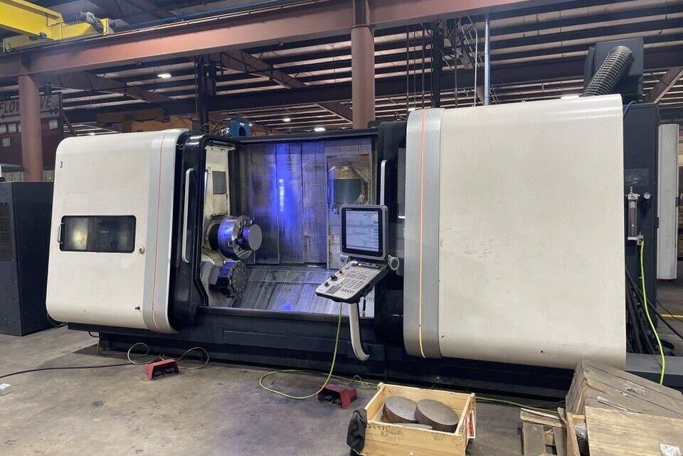
1) Machine Overview
The DMG MORI CTX GAMMA 2000 TC represents the pinnacle of hybrid multitasking technology—combining high-precision turning, 5-axis milling, and simultaneous machining within a single setup. Jointly developed in Bielefeld (Germany) and Iga (Japan), the CTX GAMMA 2000 TC is designed for complex aerospace, automotive, energy, and mold components requiring tight tolerances, perfect surface finishes, and complete part machining without reclamping.
Its integrated B-axis milling spindle, twin-spindle configuration, linear scales, and thermal-symmetrical monoblock bed enable micron-level accuracy over large part lengths (up to 2 m).
2) Key Technical Specifications to Verify
Feature
Specification
Inspection Focus
Main Spindle (Left)
4000 rpm, 38 kW / 480 Nm
Check noise, vibration, and orientation accuracy
Counter Spindle (Right)
5000 rpm, 29 kW / 320 Nm
Verify synchronization and clamping repeatability
B-Axis Milling Spindle
12 000 rpm (HSK-A63 / CAPTO C6)
Indexing repeatability ≤ ±0.001°
X / Y / Z Travel
750 / ±120 / 2050 mm
Smooth motion and backlash < 0.005 mm
C-Axis
0.0001° resolution
Check servo stability during contouring
Tool Magazine
80–120 tools
Cycle 20× tool changes – no mis-indexing
CNC Control
CELOS / Siemens 840D Solution Line
Inspect screen, keyboard, and alarm history
Machine Weight
~17 tons
Ensure foundation and leveling integrity
3) Structural Integrity & Mechanical Evaluation
Bed / Base Casting: DMG MORI’s monolithic, rib-reinforced design. Inspect for cracks, paint blistering, or oil seepage.
Linear Guideways: Ball-roller type; should show uniform lube film and no scoring.
Ball Screws: Listen for axial backlash or dry rolling noise; verify < ±0.005 mm reversal error.
Way Covers / Bellows: Must move smoothly—damage here often leads to encoder contamination.
Tailstock / Steady Rest: Check parallelism to spindle and clamp repeatability if equipped.
4) Spindle & B-Axis Head Accuracy Tests
Test
Method
Target Value
B-Axis Index Repeatability
0° → 180° → 0° cycle
≤ ±0.001°
Main Spindle Runout
Test bar at gauge length
≤ 0.003 mm
Sub-Spindle Runout
Dial indicator on chuck face
≤ 0.004 mm
Spindle Thermal Drift
1 hr @ 6000 rpm
≤ 5 µm
Drawbar Force (HSK/CAPTO)
Tension gauge
≥ 70 % of nominal
Spindle Vibration Spectrum
Accelerometer reading
No spikes at bearing bands
5) Axis Motion & Geometric Accuracy
Verification
Tool / Method
Acceptable Limit
Positioning Accuracy (X/Y/Z)
Laser interferometer
±0.005 mm / 300 mm
Repeatability
10× move test
±0.002 mm
Squareness (X–Z / Y–Z)
Autocollimator / granite square
≤ 0.01 mm per 1 m
Circularity (Ballbar)
100–300 mm radius
≤ 0.015 mm
Synchronization (Main ↔ Sub)
Dual-spindle cut test
≤ 0.01 mm phase error
Linear Scale Check
Encoder diagnostics
No lost counts or thermal drift alarms
6) Control System & Electronics
CELOS / Siemens 840D Control: Boot without NC/PLC alarms.
Verify backups of NC parameters, tool offsets, and axis calibration data.
Review alarm history—avoid units with recurring “Encoder Fault”, “Servo Overload”, or “Thermo Compensation Error”.
Inspect servo drive temperatures, fans, and cabinet cleanliness.
Ensure Ethernet, USB, and fieldbus interfaces function properly.
7) Hydraulics, Pneumatics & Cooling
System
Key Checks
Notes
Hydraulics
Clamp/unclamp speed, pressure stability
Should be quiet & consistent
Lubrication
Manifold flow & oil color
All points receiving flow; no leaks
Coolant
Pump flow, filter condition
Clean, no foaming or chips
Air Supply
FRL unit 6–8 bar
Dry, regulated air for chuck & ATC
Chiller System
Temperature differential
±1 °C range for B-axis and spindles
8) Step-by-Step Inspection Procedure
A. Static Checks
Verify machine level, anchor bolts, and bed twist using precision level.
Inspect taper sockets, turret faces, and tool clamping cones for corrosion.
Open way covers and inspect lubrication traces on linear rails.
B. Power-On Tests
Home all axes—check for stable zero return.
Warm up spindles to operating temperature.
Run through full travel at 25 %, 50 %, 100 % rapid speeds.
Test tool change × 20; verify smooth motion.
Perform synchronous turning between spindles.
Index B-axis ±90°; observe load meter stability.
C. Cutting Verification
Machine a demo part combining turning + 5-axis milling.
Measure roundness, concentricity, and surface finish.
Check dimensional drift after 1-hour run for thermal stability.
9) Common Wear & Failure Patterns
B-Axis Harmonic Drive Wear: Head deflection or backlash in milling mode.
Main Spindle Bearing Noise: Audible at 3000–6000 rpm = rebuild likely.
ATC Arm Mis-indexing: Caused by pneumatic valve wear or encoder offset.
Y-Axis Linear Rail Scoring: Often due to improper lubrication.
✅ Serial plate photo and build year verified ✅ B-axis and spindle chillers working ✅ All axes travel full stroke error-free ✅ Spindle run test (0 → 12 000 rpm) completed ✅ ATC tool change tested 20× successfully ✅ Laser or ballbar report available ✅ Control keys and screen intact ✅ Manuals, schematics, and toolholders included
Pro Tip
For the CTX GAMMA 2000 TC, prioritize machines that have:
Units maintained under DMG MORI preventive-service contracts or operated in temperature-controlled aerospace environments retain the original sub-5 µm accuracy and deliver long-term reliability.