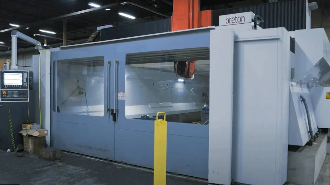
Technical Evaluation Guide: How to Identify a Quality Used, Secondhand, Pre-Owned, Surplus Breton Eagle 1500/2T CNC 5 Axis Machining Center made in Italy
1. Reference / Baseline Information & Design Context
Before evaluating, it helps to know what a healthy Eagle 1500/2T is supposed to deliver. Here are some known specifications and design traits:
- Breton markets the Eagle line as a high-speed 5-axis gantry / vertical machining center architecture optimized for composites, aluminum, resins, and light alloys.
- The listing for a used unit: 2017 Breton Eagle 1500/2T SK60 shows:
• X = 236″ (~5,995 mm), Y = 98.4″ (~2,500 mm), Z = 59″ (~1,500 mm)
• Spindle up to 28,000 rpm, tool taper HSK 63, 55 HP spindle motor, ATC 30 stations - A machine catalog indicates the Eagle 1500/2T is offered in several tool taper options (K 20/30/45/60/80/105) and in 5-axis interpolated versions.
- The machine’s structural design: welded steel, FEA-optimized, with a gantry / crossbeam architecture to reduce vibration and maintain stiffness.
- Typical performance requirements: high acceleration, high feed rates in X/Y (~70 m/min), Z (~50 m/min) for dynamic work.
From that, one sees the Eagle 1500/2T is a large-format, high-speed, high-precision 5-axis machine. Its value is in how tightly its axes, spindles, rotary axes, and control still perform in concert.
Any used machine you assess must be close to its original dynamic alignment, stiffness, spindle health, rotational axes precision, and control integrity.
2. Subsystems to Inspect & Evaluation Criteria
Below is a breakdown of major subsystems / components you must inspect, with what to measure, how to test, and tolerable vs red-flag indicators.
| Subsystem | What to Inspect / Test | What Good / Acceptable Looks Like | Warning Signs / Red Flags | Consequences / Cost Impact |
|---|---|---|---|---|
| Machine Structure, Frame, Gantry / Crossbeam | • Examine the welded structure, beams, gantry, supports for cracks, distortions, weld repairs, alignment shifts • Check for any signs of past collisions or damage • Use a straightedge / levels to detect bending or twist • Measure flatness and squareness of key reference surfaces (e.g. machine bed, column, guide rails) | Slight cosmetic wear is expected; but structure should be rigid, without visible deformation or major repairs | Warps, cracks, misaligned beams, poor welds, asymmetry between sides | Structural problems degrade precision, cause misalignment in axes, may require re-welding, re-scraping or rebuilding |
| Linear Axes (X, Y, Z) – Guideways, Ball Screws, Drives | • Inspect guideways / linear rails / ways for wear, scoring, chipping • Move axes manually (jog) and feel for binding, stick/slip • Measure backlash in each axis at multiple positions • Use test artifacts (e.g. gage blocks, dial indicators) for positional repeatability • Check ball screws / feed screws for end play, nut wear • Inspect lubrication / automatic lubrication systems • Check drive motors, couplings, alignment, encoder feedback | Guide surfaces should be smooth and consistent, backlash within spec, smooth bidirectional travel, consistent motion over full stroke | Deep scratches, localized wear, excessive backlash, uneven motion, degraded lubrication | Loss of precision across the travel, poor repeatability, inability to hold tight tolerances, expensive re-scraping or guide replacement |
| Spindle & Milling Head | • Run spindle at multiple speeds (idle) – listen for noise, vibration • Use dial indicator to check runout (axial & radial) at taper and tool tip • Test under light cutting load (if allowed) • Inspect spindle housing, seals, cooling / lubrication lines • Check for temperature rise during operation • Inspect spindle motor (e.g. insulation, bearings, windings) • If the machine has multiple spindle heads or tilting heads, test them too | Low runout, minimal vibration, stable behavior, acceptable temperature rise | High runout, noise, vibration, bearing wear, overheating, oil leaks | A worn spindle is costly to rebuild or replace; degraded surface finish, chatter, inability to hold tolerances |
| Rotary / Rotary Axes (B / C / Tilt / Trunnion) | • Rotate axes through full travel and test it in both directions • Check for backlash, indexing accuracy, repeatability • Use test artifacts (flat plates, spheres) to measure positional accuracy at various rotations • Check encoders, resolvers, feedback sensors • Check for binding, play in the rotary joints, gaskets, bearings • Check for wear at joint surfaces, lubrication of rotary axes | Smooth indexing, minimal backlash, tight repeatability (within design tolerances) | Poor indexing, sloppiness, backlash, worn encoder feedback, position drift | Misalignment in 5-axis operations, poor surface quality, inability to maintain toolpath integrity |
| Motion Control, CNC & Interpolation Systems | • Power up the CNC control & interface; check LEDs, alarms, self-tests • Exercise axis homing, limit switches, linear axis moves • Test 5-axis simultaneous motion (if machine supports full simultaneous) in dry run • Check interpolation behavior, look for signs of miscoordination or jerks • Inspect control modules, drives, wiring, patching, spares • Check for backup, firmware version consistency, memory integrity • Review error/ alarm history if available | Smooth coordinated multi-axis motion, stable control behavior, reliable feedback All axes respond without stalling or errors | Control faults, mis-interpolation, missing modules, inconsistent error history | If the control or interpolation is failing, the machine may be unusable; repairs to the CNC or cards may be expensive or impossible |
| Tool Changer (ATC) & Tool Magazine | • Cycle the tool changer through its full range, test insertion / removal • Check mechanical robustness, repeatability, indexing • Inspect gripper mechanisms, sensor feedback, magazine condition • Listen for abnormal noise, binding, mis-sequencing • Check for wear on slots, cams, guides | Smooth, timely tool changes, no misfeeds, precise tool seating | Slow, noisy, misfeeds, failed picks, magazine slot damage | Tool change failures or misalignment will lead to downtime, scrap, or crashes |
| Coolant / Lubrication / Chip Handling | • Test coolant pump(s), flow, pressure, filtration, hoses • Check coolant nozzles, through-spindle coolant (if present) • Inspect lubrication system: central / automatic lube, line integrity, valves • Check chip conveyor / chip trays, removal paths • Check for leaks, contamination, clogged lines | Stable coolant flow, healthy filtration, functional lubrication, good chip evacuation | Leaks, clogged filters, low coolant pressure, poor chip removal | Poor cooling or lubrication shortens tool and bearing life; poor chip removal may interfere with motions, cause jamming |
| Electrical, Wiring, Drives & Power Systems | • Inspect wiring, cable trays, conduits, connectors for wear, overheating, insulation issues • Power up drives, observe behavior, error lights • Check servo drive modules, inverters, motor controllers • Monitor motor currents, voltage stability, grounding, phase balance • Use thermal imaging (if possible) during idle / light motion to detect hot spots | Clean wiring, no burnt insulation, stable electrical parameters | Overheated wires, loose connections, patched wiring, grounding faults | Electrical faults lead to unpredictable behavior, downtime, risk of damaging components |
| Accuracy / Geometric Tests & Calibration | • Use test artefacts: granite squares, gage blocks, precision spheres • Conduct grid/box tests: move in X-Y plane at various Z heights and measure deviations • Rotate a part 180° and re-measure features (bidirectional check) • Use rotary-axis calibration tests: clamp a sphere, rotate B/C, measure locus errors • Check for orientation / squareness errors between linear and rotary axes • Monitor for cumulative error over travel | Deviation close to original specs or within acceptable tolerance (depending on use) No large drift or runout after motion | Large geometric deviations, drift, error accumulations, miscalibrated axes | If geometry is off beyond correction, quality of parts will suffer; expensive to realign or rebuild |
| Test Machining / Proof Cuts | • Run a proof program with a representative workpiece (or test block) • Perform simultaneous 5-axis moves if machine supports that • Measure part for tolerances, surface finish, consistency across different orientations • Monitor spindle load, current draw, temperature drift, vibration during cuts • Run extended test (several hours) to check for thermal and mechanical stability | Parts remain within tolerances, surfaces are acceptable, currents stable, no abnormal drift | Loss of tolerance, chatter, tool deflection, current surges, thermal drift | If actual machining fails, the machine’s value as a production tool is much reduced |
| Wear / Consumables / Spare Part Life | • Inspect the degree of wear on key wear components: spindle bearings, linear guides, rotary axis bearings, seals, coupling elements • Determine how many remanufacturing cycles remain • Ask for records of part replacements (bearings, guides, spindles, encoders) • Check availability of spare parts (especially for control modules, drives, encoders, spindle internals) | Uniform and moderate wear, documentation of past maintenance Spare parts availability | Excessive wear, parts at end-of-life, missing or obsolete parts | Major expense to replace broken parts or refurbish; spare parts may be unavailable or very costly |
| Documentation, Control / Program History, Service Records | • Ask for as-built drawings, wiring diagrams, mechanical & electrical schematics • Ask for maintenance logs, part replacement history, calibration records • Ask for software versions, control licenses, backup copies, tool libraries • Look for records of crashes, repairs, modifications | Complete, consistent, professional documentation Good control history, backups, no unexplained gaps | Missing or inconsistent records, unknown modifications, missing software licenses | Unknown repair history increases risk; missing documentation may hamper future servicing or upgrades |
| Safety, Access, Maintenance, Guarding | • Inspect safety guards, covers, interlocks, doors • Check access to critical components (spindle, rotary axes, drive modules) for servicing • Confirm emergency stops, protective circuits, lock-out mechanisms • Check cleanliness, dust / chip control, filter enclosures, cooling system vents | Good safety interlocks, easy service access, clean environment, proper guarding | Missing guards, unsafe access, blocked maintenance paths | Safety hazards, increased downtime, difficulty in servicing |
3. Suggested On-Site Inspection & Check Sequence
To make your onsite inspection structured and effective, here’s an ordered walk-through you can follow (with tools / instruments you should bring):
- Preliminary Walkaround & Documentation Collection
– Photograph all sides, nameplates, serial numbers, model plates
– Note visual signs: dents, repairs, missing covers, alignment shifts
– Collect any manuals, schematics, service logs available - Power-On / Control Basic Check (No Load / Dry Run)
– Boot CNC, check for warnings / alarms / errors
– Jog linear axes slowly, check smooth motion
– Home axes, check limit switch functionality
– Command small simultaneous 5-axis moves (if possible) in dry run
– Open control diagnostics, check servo status, alarm logs - Spindle Run / Noise / Vibration Check
– Start spindle (low, medium speed), listen & feel for vibration or noise
– Use dial indicator to measure runout at spindle taper
– Run at higher speeds (if safe) and monitor temperature - Axis Motion & Backlash / Repeatability Tests
– Jog each axis over incremental distances, reverse, measure backlash – Move to multiple positions and command the same move to test repeatability
– Inspect motion manually, feeling for binding, stick/slip - Open & Inspect Mechanical Internals
– Open access panels when safe & locked-out – Inspect ball screws, guides, coupling alignment, lubrication lines – Check for damage, wear, chipping on guide surfaces - Rotary Axis / Trunnion Tests
– Rotate B / C axes fully, both directions – Index to test positions and back-check – Mount test sphere / part to check locus errors - Tool Changer / ATC Operation
– Run ATC cycles, load/unload tools, watch timing and accuracy – Check magazine mechanical condition - Coolant / Lubrication / Chip Handling
– Start coolant pumps and filtration, observe nozzles working – Start chip conveyor, check cleanliness, jam possibilities – Check all lines, hoses, valves - Drive & Electrical System Check
– Open electrical cabinet, visually inspect wiring, connectors – Start axis drives, monitor current, noise, and temperature – Use handheld meter or thermal camera (if available) to scan for hotspots - Test Machining / Cutting Trial
– Run a representative program with a test block / workpiece – Use simultaneous 5-axis features if relevant – After machining, inspect the part (dimensional measurements, surface finish) – Run for extended time (1–2 hours) to see stability over duration - Geometric Accuracy / Calibration Tests
– Using certified artifacts, perform grid tests, measurement at different Z levels – Rotate parts 180°, 90°, check positional consistency – Use sphere test / rotational error test for B/C axes - Review Service Records & Parts History
– Go through logs, find part replacement history – Ask about major repairs, crashes, refurbishments – Match serial numbers of components (drives, spindles, encoders) to records - Estimate Repair / Refurbishment Needs & Negotiation
– Based on inspection, list required repairs or wear-item replacements – Discount the asking price accordingly – Add acceptance conditions: e.g. must meet certain dimensional accuracy, vibration limits, or proof-cut performance before payment
Bring tools: dial indicators, test bars, micrometers, runout gauges, vibration meter (if available), flashlight, infrared thermometer or thermal camera, decibel meter, torque wrench, alignment straightedge, etc.
4. Red Flags / Deal Killers (What to Watch Out For)
Here are some conditions that should make you extremely cautious, ask for steep discounts, or reject the machine:
- Spindle with high runout, noise, or overheating
- Rotary axes (B / C) with excessive backlash, poor indexing, or failing encoders
- Deep wear, scoring, or chipping on guideways or linear rails
- Excessive backlash or play in ball screws / drive system
- Control faults, missing modules, error history, unsupported or custom controller
- Tool changer failures or magazine damage
- Cooling / lubrication system inoperative or clogged
- Electrical wiring highly patched, burned insulation, overheating signs
- Significant past crash or collision damage, hidden structural repairs
- Geometry drift or large deviations in calibration or proof-cut
- Obsolete parts or modules (electronics, drives, encoders) that are no longer available
- Lack of maintenance history or missing documentation
- Poor service access or safety compliance issues
- Inability to perform a valid proof-cut to acceptable tolerances
If any of these are present without justification, they dramatically increase your risk.
5. Risk Mitigation & Negotiation Suggestions
- Always insist on a proof-cut acceptance test: e.g., they must run a real part for, say, 2 hours and deliver a part that meets your dimensional tolerances, finish, and stability criteria.
- Factor in a refurbishment / repair budget: even a “good” used 5-axis machine may need new bearings, recertification, control board replacements, balancing, alignment.
- Negotiate based on defects: e.g. if the spindle shows moderate wear, reduce price by the cost of spindle rebuild plus margin for margin of error.
- Ensure you receive all control backups, programs, licenses, configuration files, wiring diagrams, parts drawings as part of the sale.
- If possible, get a “day in the life” run under real production feedstocks to stress-test the machine in its intended use.
- Engage a 5-axis / metrology expert for final acceptance: someone who can spot subtle misalignments or interpolation errors.
- Check local availability of spare parts (spindle internals, rotary axis bearings, encoders, drive modules) in your country / region.
- Include contractual clauses: e.g. if the machine fails to meet agreed performance metrics within a given period, buyer has recourse or returns.
- Include a warranty period (if seller can provide) even for used machines (e.g. 30–60 days) for hidden issues to surface.