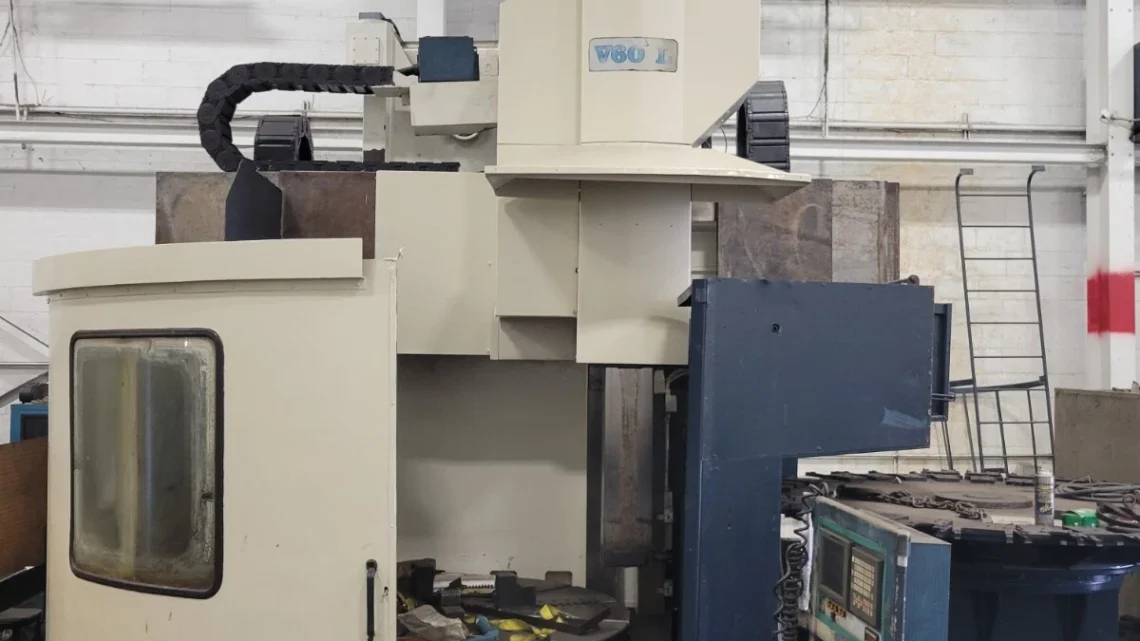
Technical Buyer’s Handbook: Assessing Pre-Owned , Used , Secondhand, Surplus CNC Machines Before Purchase OLYMPIA V60L CNC Vertical Turning Center C-Axis made in Germany
Below is a Technical Buyer’s / Due-Diligence Handbook / Inspection Guide you can use (and adapt) when assessing a pre-owned, used, or surplus OLYMPIA V60L CNC Vertical Turning / Vertical Turret Lathe (VTL) with C-axis (made in Germany). Use it as a structured checklist; adjust tolerances, weighting, and test depth based on your precision / production needs.
I also include some benchmark specifications from listings to help you set expectations.
0. Reference / Benchmark Specifications (OLYMPIA V60L)
Before visiting the site, gather the exact spec sheet for the unit (serial, options) so you have baseline targets. Below are some published specs from used listings for V60L machines:
| Parameter | Typical / Published Value |
|---|---|
| Table / Chuck diameter | 66″ (≈ 1680 mm) |
| Maximum swing / turning diameter | ~ 68″ (≈ 1727 mm) |
| Maximum under rail height | ~ 70″ (≈ 1778 mm) |
| Vertical ram travel (Z) | ~ 40″ (≈ 1,016 mm) |
| Cross-rail / horizontal travel | ~ 40″ (≈ 1,016 mm) |
| Live tooling (milling) speed | 2,500 rpm (CAT-50) |
| Main spindle speed / rotational table speed | up to 350 rpm (table) |
| Spindle / table drive power | 50 HP (approx) |
| Tool magazine / ATC capacity | 32 tools standard |
| Weight | ~ 58,000 lbs (≈ 26,300 kg) |
| Footprint / dimensions | ~ 200″ × 180″ × 140″ (L × W × H) in some listings |
These are target values. On inspection, deviations may indicate wear, modifications, or missing options.
I. Pre-Inspection / Remote Work
Before going to the site, collect as much information and documentation as possible:
- Full mechanical, electrical and control manuals (wiring diagrams, interface maps, logic diagrams)
- Maintenance and repair logs (spindle rebuilds, column/rail refurbishment, turret issues)
- Alignment / calibration / geometric inspection reports
- Records of modifications, retrofits, or upgrades (live tooling, C-axis, additional drives)
- Spare parts list / BOM and any tool / fixture inventory
- High-resolution photos / videos: overall machine, spindle, rails, turret, tool magazine, interior of cabinets, wiring
- Motion videos if machine is still operational (axis jogs, live tool spin, C-axis rotation)
- Key questions: year, serial number, total run hours, known faults, accessory options, control type, whether it is currently operational
Bring or arrange to have:
- Dial indicators, test bars, precision squares, straight edges
- Laser alignment / interferometer tools (if available)
- Vibration / accelerometer sensor
- Thermography / IR camera
- Tools to open panels / inspect circuit boards
Check logistical constraints: machine weight, rigging access, foundation strength, power supply, coolant / chip removal systems, clearance for movement and servicing.
II. Static / Structural Inspection (Power-Off)
Before powering, inspect all structural and mechanical systems thoroughly.
1. Frame, Bed, Columns, Castings
- Inspect base, column, bed, castings for cracks, weld joints or repairs, distortions
- Look for signs of foundation rework (shim stacks, uneven supports)
- Inspect for corrosion, pitting, especially in coolant / chip splash zones
- Examine covers, guards, way covers, bellows, seals — missing parts or damage
2. Guide Rails, Linear Slides, Carriages, Ball Screws (if used in axes)
- Check rails / guide surfaces for wear, scuffing, pitting, scoring
- Inspect carriage blocks / slides for looseness, side play, binding
- Check ball screws, nuts, couplings (if Y-axes or cross-rail) for backlash or wear
- Manually (if safe) move axes and feel for friction, unevenness
- Inspect lubrication lines, fittings, blockage, leakage
3. Spindle / Table / Rotary Mechanism
- Inspect the table / rotary drive surfaces, bearings, thrust bearings, sealing
- Inspect the spindle drive / drive shaft, coupling interfaces, seals
- Check table bearing condition, mounting integrity
- Insert a test bar (non-driven) on the table / chuck if possible for static run-out check
4. Live Tooling / Milling Spindle (if installed)
- Inspect live tooling spindle, collet / taper interface, seals, bearings
- Check the tooling drive, coolant / lubrication lines, feedback sensor wiring
- Inspect the mechanical structure of the live tool mounting for rigidity
5. Tool Magazine & Tool Changer
- Inspect tool magazine pockets, indexing mechanism, alignment, wear
- Examine tool changer arms, slides, grippers, sensors, actuators
- Check mechanical alignment, backlash, sensor states
6. Electrical / Control Cabinets, Wiring & Components
- Open cabinets if permitted and inspect wiring joints, terminal blocks, connectors
- Look for heat damage, melted insulation, discolored wires
- Inspect drive modules, control boards, I/O modules for damage or dust
- Check fans, filters, ventilation paths
- Examine cable carriers / drag chains in motion zones
7. Safety Interlocks, Limit / Home Switches, Emergency Stop
- Confirm presence and integrity of Emergency Stop (E-stop) devices
- Inspect guard doors and interlock switches
- Check limit / home switch condition for axes and C-axis
- Ensure no safety bypass wiring present
III. Power-Up & Dynamic / Functional Testing
Once the static inspection is acceptable and safety is assured, power up and execute controlled dynamic tests.
1. Control Startup & Diagnostics
- Power on control / CNC, monitor boot sequences, alarms, error logs
- Confirm all CNC parameters, compensation tables, offsets load correctly
- Check I/O input states: limit, home, interlocks, sensors
- Jog axes slowly at low feed to check smooth motion, correct direction, no binding
2. Homing / Reference / Zero Moves
- Execute homing / reference cycles for all axes (X, Y, Z, C-axis)
- Repeat homing multiple times to verify consistency of home positions
- Trigger limit switches to test safe stops
3. Axis Traversal & Accuracy
- Move axes over full safe travel (within limits) to test smoothness
- Program precise incremental moves (e.g. 100 mm or inch values) and measure using dial indicator or laser device
- Reverse direction and check for backlash / mechanical dead zone
- Run combined multi-axis moves (if control supports) to test coordination
4. Spindle / Table / Rotary Performance
- Start the table / spindle drive at low rpm, observe for vibration / noise
- Gradually increase to higher speeds; monitor behavior
- If possible, mount a test workpiece for rotational run-out measurement
- Check for torque stability, motor current draw, thermal behavior
5. Live Tool / Milling Spindle Test
- Activate live tool spindle, run at varying speeds, check for smoothness, vibration
- Test tool actuation (start / stop, spindle direction reversal if applicable)
- Monitor coolant / lubrication supply during operation
6. Tool Change Sequence & Magazine Test
- Execute multiple tool change cycles; observe timing, sensor feedback, smoothness
- Repeat tool changes many times to detect intermittent faults
- Try various tool sizes / lengths within allowable range
7. Sample Machining / Part Test
- If possible, perform a light machining operation (e.g. face milling or boring) on a sample workpiece
- Compare part geometry with programmed path, inspect surface finish
- Run multiple cycles to observe thermal drift, dimensional shift
- Monitor vibration or anomalies during cutting
8. Safety / Fault Response Tests
- Trigger E-stop mid-motion, spindle, or tool change: machine must stop cleanly
- Activate limit switches or simulate sensor failures to test fault responses
- Open guard doors during idle / safe mode to test interlocks
9. Stability / Warm-up / Drift Tests
- Let the machine run idle or move for ~30–60 min to allow thermal effects
- After warm-up, re-test key positions, backlash, repeatability to detect drift
- Monitor motor, cabinet, spindle temperatures
- Use thermography or vibration sensors to locate hot spots or anomalies
IV. Precision, Calibration & Accuracy Validation
Once thermally stabilized, perform high-precision checks to determine machine capability.
- Repeatability test: move to a point, retract, return, and measure deviation
- Grid / mapping test: command a mesh of positions (X, Y, Z) and measure the actual positions to plot error across working envelope
- Squareness / orthogonality tests: e.g. moving in X then Z vs Z then X to detect misalignment
- C-axis accuracy / angular repeatability: test indexed rotations for backlash, angular precision
- Combined machining test: use live tool in combination with turning / milling operations, then measure combined geometry deviation
- Testing under offset or varying load conditions (heavier workpiece, unbalanced forces) to check stiffness and deflection
- Use laser interferometer, dial gauges, reference spheres, or other metrology tools if available
- Compare your measured deviations against machine’s original specifications or your acceptance tolerances
V. Documentation & Service / Repair History Review
After mechanical/dynamic tests, review the documentation and history to understand machine provenance and risk.
- Maintenance / repair records: spindle rebuilds, major overhauls, component replacements
- Calibration / alignment / geometric inspection certificates
- Retrofits, upgrades, control changes, live tooling addition
- CNC / control software versions, backup programs, parameter files
- Spare parts inventory (bearings, rails, tool holders, electronics)
- Tooling, fixtures, collets included
VI. Risk Assessment, Life-Remaining Estimate & Cost Projection
From your inspection and test results, build a risk model and cost forecast.
- High-wear subsystems: table bearings, ram / cross rail slides, live tooling bearings, seals
- Difficulty / cost of spare parts for Olympia / German VTL machines
- Calibration, alignment, compensation cost after transport
- Transport / installation risk: shock to heavy components, re-alignment of columns, tables
- Commissioning / downtime cost
- Control / electronics obsolescence risk
- Salvage value of structure / casting if machine is unusable
You may implement a weighted scoring matrix across subsystems (structure, axes, spindle / rotary, live tooling, control) to guide what you are willing to pay and the repair buffer.
VII. Contractual Safeguards & Negotiation Clauses
Use your inspection as leverage to negotiate protective contract clauses.
- Acceptance / test clause: final sale contingent on passing all functional, dynamic, and precision tests after installation
- Price adjustment clause: allow deductions for deviations beyond agreed tolerances
- Warranty / latent defect clause: guarantee hidden defects for a period (e.g. 3–6 months)
- Spare parts / tooling package requirement: require inclusion of critical wear parts (bearings, seals, tool holders)
- Documentation clause: require delivery of manuals, wiring diagrams, control backups, alignment reports
- Transport / insurance clause: clearly assign liability for damage during shipping, unloading
- Commissioning / support clause: require seller or OEM technician support for initial setup, calibration
VIII. Post-Purchase / Installation & Commissioning Checklist
Once the machine is delivered and set up, follow a disciplined commissioning process.
- Level, anchor, and align foundation / base / frame
- Clean, flush, and commission lubrication / coolant / hydraulic systems; replace filters / fluids
- Verify all connections, safety interlocks, cables, guards, wiring
- Power up and re-run full acceptance / dynamic / precision test suite
- Perform alignment, geometric calibration, error compensation mapping
- Run test parts using your real materials to validate performance under production loads
- Record baseline metrics: backlash, repeatability, drift, temperature behavior
- Train operators and maintenance personnel on machine specifics, quirks, procedures
- Establish preventive maintenance scheduling (bearing checks, alignment checks, lubrication audits)
- Monitor performance carefully for first production weeks to detect drift, anomalies, deviations