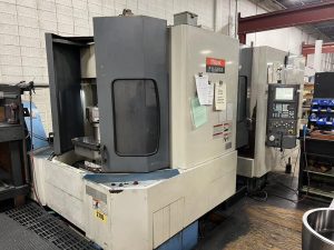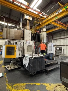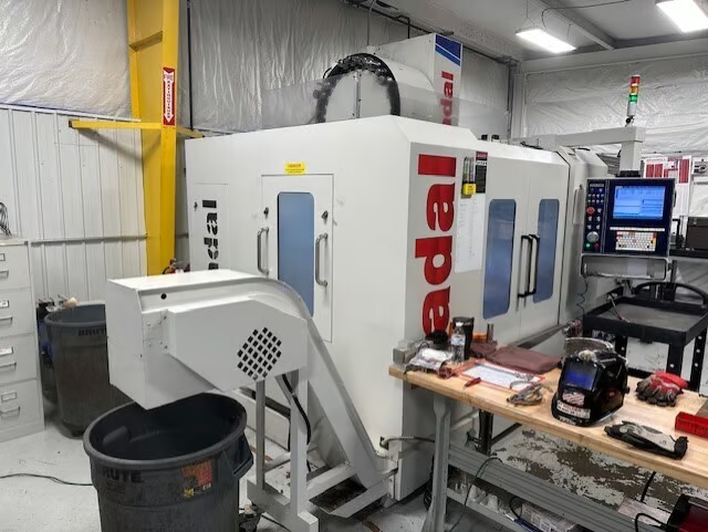
Technical Buyer’s Handbook: Assessing Pre-Owned , Used , Secondhand, Surplus CNC Machines Before Purchase Fadal VMC 4020B-II CNC Vertical Machining Center made in USA
Here is a Technical Buyer’s Handbook / Due-Diligence Checklist tailored for evaluating a Fadal VMC-4020B-II vertical machining center (CNC vertical mill, made in USA). Use it as a structured guide; adjust tolerances, priorities, and weightings to match your application, precision needs, and budget.
I also include benchmark specs from manufacturer / listings so you know the typical performance envelope.
0. Reference / Benchmark Specifications
Before inspecting onsite, gather or confirm the official spec sheet (serial / option set). Below are typical published specs for the Fadal VMC-4020B-II:
| Parameter | Typical / Published Value |
|---|---|
| X-axis travel | 40 in (≈ 1,016 mm) |
| Y-axis travel | 20 in (≈ 508 mm) |
| Z-axis travel | 20 in (508 mm); optional extended 30 in (762 mm) |
| Table size | 47.25 in × 19.75 in (≈ 1,200 mm × 500 mm) |
| Maximum table load | ~ 1,320 lb (≈ 600 kg) |
| Spindle speed | 10,000 rpm standard |
| Spindle (peak) power | 15 hp (≈ 11.2 kW) nominal, possibly 22.5 hp peak version |
| Rapid traverse (X / Y / Z) | 1,000 in/min (≈ 25,400 mm/min) |
| Tool magazine / changer | 24-station dual-arm ATC (with options for 30 or 40) |
| Construction / guideway type | Heavy box-way / hardened & ground box members; non-metallic liner gibs |
| Machine dimensions (L × W × H) | 109 in × 87 in × 110 in (without chip conveyor) |
| Machine weight | ~ 11,770 lb |
These are reference “target” values. A used unit will deviate; your task is to assess whether deviations are acceptable, repairable, or deal-breakers.
I. Pre-Inspection / Remote Preparation
Before visiting, do as much research and preparation as possible to minimize surprises:
- Request documentation
- Mechanical, electrical, and control (CNC) manuals
- Wiring schematics, I/O maps, axis compensation files
- Maintenance / repair logs (spindle rebuilds, ATC repair, guide refurb)
- Alignment / calibration / geometric inspection records
- Option / retrofit history (extended Z, high torque spindle, pallet changer)
- Spare parts list, tooling list - Photos & videos
Ask for high-resolution photos / video of:
- Overall machine (front, sides, top)
- Table surface, T-slots, underside
- Spindle nose, head, tool changer area
- Guideways, carriage, axes, lead screws
- Control / electrical cabinets, drives, wiring
- If possible, video of axis jogging, tool changes, spindle running - Ask key questions
- Year, serial number
- Total machine run hours / spindle hours
- Operational status (still works?)
- Known faults, collisions, repairs
- Which options or upgrades are installed (4th axis, pallet changer, thru-spindle coolant)
- Control version, backup program state - Bring inspection instruments / tools
- Dial indicators, test bars, straight edges, micrometers
- Laser alignment / interferometer tools (if available)
- Vibration / accelerometer sensor
- IR / thermography camera
- Torque wrenches, feeler gauges
- Tools to open cabinets - Logistics & site constraints
- Machine weight, rigging / crane access
- Floor foundation capacity, leveling options
- Power supply (voltage, phases, amps)
- Coolant, chip handling, exhaust, coolant pumps
- Space clearance, maintenance access
II. Static / Structural Inspection (Power-Off)
Before powering anything, inspect all structural, mechanical, and visible subsystems carefully.
1. Frame, Bed, Structure, Castings
- Inspect base, column, casting, frame for cracks, weld repairs, distortions
- Look for shimming / leveling repairs, signs of foundation movement
- Check for corrosion, coolant damage, pitting in splash zones
- Examine machine covers, guards, way covers, bellows, seals
2. Linear Guides, Carriages, Lead Screws
- Inspect guide surfaces for wear, scuffing, pitting, spalls
- Check carriage blocks / slides for looseness or play
- Inspect lead screws / ball screws, nuts, couplings for backlash or wear
- Move axes (by hand, if safe) over travel to feel for binding or friction
- Inspect lubrication system: lines, fittings, leaks, blockages
3. Spindle / Head / Tool Interface
- Inspect spindle nose, taper surfaces, clamping surfaces for wear or damage
- Check spindle head housing, seals, cooling lines, for leaks
- If possible, mount a test bar (non-rotating) to check static run-out
- Inspect lubrication / coolant lines to spindle
4. Tool Changer & Magazine
- Inspect magazine pockets, indexing mechanism, arms, slides for wear
- Check grippers, actuators, sensor alignment, mechanical condition
- Cycle tool changer (if safe) for smooth motion
5. Electrical Cabinets, Drives, Wiring
- Open cabinets (if allowed) and inspect wiring, terminal blocks, connectors
- Look for heat damage: discolored wires, burnt insulation
- Check control / drive boards, I/O modules, power modules for dust, damage
- Inspect fans, filters, ventilation
- Check cable carriers, drag chains, moving wiring
6. Safety Interlocks, Limit / Home Switches
- Verify presence and mechanical integrity of E-stop (emergency stop) buttons
- Inspect guard doors, interlock switches
- Check limit / home switches for axes
- Ensure no bypass wiring across safety circuits
III. Power-Up & Functional / Dynamic Testing
Once static inspection passes (or is acceptable) and safety is assured, power up and run dynamic tests.
1. Control & Diagnostics
- Power on CNC / control; observe boot sequence, alarms, errors
- Verify parameter files, offset tables, compensation maps load correctly
- Check I/O status: limit / home / safety inputs, sensor feedback
- Jog axes slowly; check direction, smoothness, no binding
2. Homing / Reference / Zeroing Moves
- Perform homing / referencing on X, Y, Z axes
- Repeat homing cycles, verify repeatability of home location
- Trigger limit switches to test response
3. Axis Traversal & Motion Behavior
- Traverse each axis over full safe travel (within limits) to test smooth motion
- Command precise moves (e.g. 100 mm) and measure with dial gauge / test device
- Reverse direction and measure backlash / dead zones
- Run combined/multi-axis moves (if control supports) to test coordination
4. Spindle / Rotational Performance
- Run spindle at low rpm, then ramp up; listen for vibration, noise
- If possible, mount test workpiece or test bar to measure run-out under rotation
- Monitor spindle motor current, stability, temperature
- Check spindle cooling / lubrication under motion
5. Tool Change & ATC Test
- Execute multiple tool change cycles; monitor timing, correctness, smoothness
- Repeat cycles to detect intermittent faults
- Try different tool sizes / lengths (within safe limits)
6. Machining / Test Cut
- Run a light milling test (e.g. in aluminum) to simulate real usage
- Compare part dimensions vs programmed path, inspect surface finish
- Let the machine run cycles to detect drift, thermal effects
- Monitor anomalies (vibration, current spikes) during cutting
7. Safety / Fault Response Tests
- Press E-stop during motion / spindle, check safe stoppage
- Trigger limit switches spontaneously to test axis behavior
- Simulate sensor failure (if safe) for error handling
- Open guard doors during safe idle to test interlock behavior
8. Stability / Warm-Up / Drift Tests
- Let the machine run idle or move cycles for 30–60 min to warm up
- After warm-up, re-check key motion points, backlash, repeatability to detect drift
- Monitor motor / control / spindle / cabinet temperatures
- Use IR / thermography or vibration sensors to detect hotspots or anomalies
IV. Precision, Calibration & Accuracy Validation
Once machine is thermally stable, do precision validation tests.
- Repeatability test: move to a point, retract, return, measure deviation
- Grid / mapping test: command multiple positions across the workspace and measure deviation
- Squareness / orthogonality checks: move X then Y vs Y then X, compare results
- Tool offset / spindle alignment checks
- Under load (heavy workpiece, long tool overhang) test deflection / compliance
- Use higher accuracy tools (laser interferometer, dial gauge, calibration bars) if available
- Compare measured errors vs acceptable tolerances or spec sheet
V. Documentation & History Review
After mechanical / functional tests, evaluate all documentation and history.
- Maintenance / repair logs (spindle rebuilds, ATC failures, guide replacement)
- Calibration / alignment certificates
- Retrofits or modifications (e.g. higher speed spindle, 4th axis, chip conveyor)
- CNC / control software version, backups
- Spare parts / tooling inventory (tool holders, spindles, belts, drives)
- Tooling, fixtures, accessories included
VI. Risk Assessment, Life-Remaining Estimate & Cost Forecasting
Based on your inspection results, build a risk / cost model.
- High-wear components: ATC mechanisms, spindle bearings, guide rails, ball screws
- Spare parts availability and cost for Fadal machines
- Calibration & alignment cost after relocation
- Cost to recondition worn components
- Transport / installation risk (shock, realignment shifts)
- Commissioning and downtime cost
- Control / electronics obsolescence risk
- Salvage / fallback value of structural frame
You can build a scoring matrix (structure, axes, spindle, ATC, control) to rate condition and guide your maximum offer.
VII. Contractual Safeguards & Negotiation Clauses
Use your findings to negotiate protective clauses in the purchase agreement.
- Acceptance / test clause: condition sale on passing your functional & precision tests after installation
- Price adjustment clause: allow deductions if performance deviates beyond agreed tolerances
- Warranty / latent defect clause: e.g. 3–6 months coverage on hidden defects
- Spare parts / tooling inclusion clause: require critical wear parts / ATC spares included
- Documentation handover clause: manuals, wiring schematics, control backups, alignment data delivered
- Transport / insurance clause: assign risk for damage during movement / unloading
- Commissioning / support clause: require the seller or OEM tech help with first alignment / calibration
VIII. Post-Purchase / Installation & Commissioning Checklist
Once delivered and installed:
- Level, anchor, and align foundation / base
- Clean and flush lubrication / coolant / chip removal systems; replace filters / fluids
- Reconnect safety interlocks, wiring, guards
- Power-up and re-run full acceptance / functional / precision test suite
- Perform alignment, geometry calibration, compensation mapping
- Run test parts in your production materials, validate tolerances
- Record baseline metrics (repeatability, drift, temperature behavior)
- Train operators & maintenance staff
- Establish preventive maintenance schedule
- Monitor performance in early weeks for deviations, trend anomalies