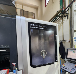
Technical Buyer’s Handbook: Assessing Pre-Owned , Used , Secondhand, Surplus CNC Machines Before Purchase DMG DECKEL MAHO DMU 70 CNC 5-Axis Vertical Machining Center made in Germany
Here is a Technical Buyer’s Handbook / Due-Diligence Guide for assessing a DMG / DECKEL MAHO DMU 70 (5-axis vertical machining center) before purchasing a used or surplus unit. Use this as an inspection blueprint; adjust tolerances, weighting, and test depth to your precision / production requirements.
I also include benchmark specs and caveats drawn from real listings for DMU 70 / “eVolution” versions to guide expectations.
0. Reference / Benchmark Specifications (DMU 70)
To know your target window, here are typical published specs for DMG/Deckel Maho DMU 70 / DMU 70 eVolution variants:
| Parameter | Typical / Published Value |
|---|---|
| X travel | 750 mm (≈ 29.5″) |
| Y travel | 600 mm (≈ 23.6″) |
| Z travel | 520 mm (≈ 20.5″) |
| Table / rotary table size | Ø 700 × 500 mm (circular table) |
| Max workpiece weight (on table) | ~ 350 kg |
| Spindle speed | Up to 18,000 rpm in many units |
| Spindle motor / power | ~ 22.5 kW (40% duty) / 15 kW continuous in some specs |
| Rapid feed (X/Y/Z) | ~ 50 m/min |
| Linear axes feed | ~ 20 m/min |
| B-axis swivel range | 0 to 180° |
| C-axis rotation | 360° with fine angular resolution (0.001°) |
| Machine weight / footprint | ~ 8,320 kg, dimensions ~ 2,574 × 5,320 × 2,829 mm (for a 2001 eVolution unit) |
| Control / options commonly seen | Heidenhain TNC-426, iTNC 530, glass scales, internal coolant-through-spindle, automatic tool changer (ATC) |
These figures are benchmarks; any candidate machine that deviates significantly should have a documented reason (e.g. retrofit, de-rated spindle, shortened travel) or be considered lower in value.
I. Pre-Inspection / Remote Preparation
Before you commit inspection-time or travel, collect as much data/documentation and evidence as possible:
1. Request Documentation
- Factory mechanical, electrical, hydraulic, and control manuals
- Wiring diagrams, I/O maps, control schematics
- CNC parameter backups, tool offset tables, compensation maps
- Maintenance / service logs (spindle rebuilds, guide replacement, rotary axis overhauls)
- Calibration / alignment / geometry inspection certificates
- Retrofits or upgrades history (spindle changes, control upgrades, measurement systems)
- Spare parts list, tooling / fixture inventory
- As-is photographs / videos: machine exterior, table, axes, rotary table, tool changer, cabinet interiors
2. Ask Clarifying Questions
- Year of manufacture, serial number
- Total running hours / spindle hours
- Operating environment and materials machined heavily
- Reason for sale / decommission
- Known issues, collisions, repairs
- Option set: e.g. coolant-through-spindle (CTS), probe systems, thermal compensation, high-speed package, glass scales
- Control type / version, software backups
- Ask for video of axes motion, tool changes, rotary table spin
3. Prepare / bring Inspection Tools
- Dial indicators, test bars, feeler gauges, precision straight edges
- Laser interferometer / alignment tools (if available)
- Vibration sensor / accelerometer
- IR / thermography camera
- Tools to open control cabinets, measure wiring continuity
- Torque wrenches, micrometers
4. Logistics Check
- Machine weight, required lifting / crane capacity
- Foundation / floor load rating, leveling possibilities
- Power supply (voltage, phases, current capacity)
- Coolant / chip removal systems, filtration, piping
- Work area clearance, access for service, door widths
II. Structural & Static Inspection (Power-Off)
Before powering, do a thorough structural and mechanical walk-around.
A. Frame, Base, Castings, Column
- Inspect base, frame, column castings for cracks, weld repairs, alignment repair marks
- Look for signs of foundation settling or shifting (shim stacks, uneven supports)
- Check for corrosion, pitting, chip / coolant damage in splash zones
- Inspect covers, way covers, bellows, seals for missing parts or damage
- Use a long straight edge or surface plate to check for twist or bending in structural members
B. Guideways, Linear Axes, Rotary / Swivel Axes
- Examine linear guideways, rails / slides for scuffs, pitting, spalling
- Check for side play or looseness in carriage blocks
- Inspect ball screws / drive screws and nuts for backlash, wear, binding
- Manually slide axes (if safe) to feel for friction, unevenness
- Inspect B / C axis (swivel / rotary table) bearings, gear teeth, disc edges for wear, backlash
- Inspect rotary table bearings/seals for damage or leakage
C. Spindle / Tool Interface
- Inspect spindle nose, taper, clamping surfaces for wear, chipping, burrs
- Check spindle housing, seals, cooling lines, lubricant leakage
- If possible, insert a test bar (non-driven) to measure static run-out
- Inspect coupling and bearing supports
D. Tool Changer / Tool Magazine
- Inspect tool magazine pockets, indexing mechanism, slides, grippers
- Check for worn or misaligned arms, slides, sensors
- Check magazine indexing, mechanical alignment
- Inspect actuator mechanisms and sensor wiring
E. Electrical Cabinets, Drives & Wiring
- Open control / drive cabinets (if permitted) and inspect wiring, terminal blocks, connectors
- Look for signs of heating damage: discolored insulation, burned parts
- Inspect drive modules, CNC boards, I/O boards for dust, damage, corrosion
- Check fans, filters, ventilation paths
- Inspect cable carriers / drag chains, moving cable wear
F. Safety, Interlocks & Limit / Home Switches
- Verify Emergency Stop (E-stop) buttons are present and mechanically functional
- Inspect guard doors, interlock switches
- Check limit / home / reference switches for each axis
- Ensure no bypass wiring circumventing safety circuits
III. Power-Up & Functional / Dynamic Testing
After static checks, power on and run dynamic / functional tests carefully, ensuring safety protocols.
1. Control Startup & Diagnostics
- Power the CNC/control; watch boot logs, alarms, error codes
- Confirm that parameters, compensation tables, tool offset maps load cleanly
- Test I/O: ensure limit, home, safety interlocks, sensors report correctly
- Jog axes slowly; check direction, smoothness, no binding
2. Homing / Reference / Repeatability Moves
- Run homing or reference cycles on X, Y, Z, B, C axes
- Repeat homing sets to test consistency / repeatability of reference positions
- Trigger limit switches to confirm safe stops
3. Axis Motion & Traverse Tests
- Move each linear axis over full safe travel (within limits) to sense smoothness
- Command precise increments (e.g. 100 mm, 200 mm) and measure with dial indicator / metrology tool
- Reverse direction and measure backlash / dead zone
- Run composite / multi-axis simultaneous moves (e.g. X + B, Y + C) to check motion coordination
4. Rotary / Swivel Table / C-Axis Tests
- Spin the C-axis at various speeds; check for smooth, uniform rotation
- Test indexing / positional repeatability of C and B axes
- Load axis under torque, and test backlash / drift
- Verify locking / braking mechanisms under load
5. Spindle / Milling Operations Test
- Run spindle at incremental rpm to check vibration, noise, run-out
- If possible, mount test workpiece / tool and do light milling / facing
- Monitor spindle motor current, thermal behavior, stability
- Check cooling / lubrication effectiveness during runtime
6. Tool Change / ATC Tests
- Execute multiple tool change cycles; check timing, correctness, gripper performance
- Repeat multiple cycles to identify intermittent issues
- Use a range of tool lengths / sizes to test flexibility
7. Machining / Sample Operation
- Program a test operation (simple milling, contouring) with moderate parameters
- Measure resulting part geometry vs programmed path; assess surface finish
- Run repeated cycles to look for dimensional drift, thermal deformation
- Monitor vibration / anomalies during active machining
8. Safety / Fault / Interlock Tests
- Trigger E-stop during motion / milling / tool change; verify safe shutdown
- Trigger limit switches out of sequence to test error handling
- Open guard doors / panels during safe mode / motion (if allowed) to test interlocks
- Simulate sensor failures (if safe) and check error recovery behavior
9. Stability / Warm-Up / Drift Test
- Allow the machine to run idle or traverse continuously for 30–60 min to let thermal equilibrium settle
- After warm-up, re-test critical points, re-check backlash and accuracy to detect drift
- Monitor motor, drive, spindle, cabinet temperatures
- Use IR / thermography or vibration instrumentation to find hotspots or latent issues
IV. Precision, Calibration & Accuracy Validation
Once the machine is thermally stable, perform precise measurement tests to evaluate its suitability.
- Repeatability test: move to a coordinate, retract, return, measure deviation
- Grid / mapping test: command mesh of points over X–Y–Z / B / C axes and measure deviations across entire envelope
- Squareness / orthogonality checks: move in one direction then another vs reverse order, check error difference
- Rotary / swivel axis angular accuracy: test C, B axes indexing and fine resolution accuracy
- Combined multi-axis machining test: e.g. simultaneous 5-axis movement, then measure resulting geometry
- Under load / extended overhang, test deflection / stiffness
- Use high-precision tools (laser interferometer, calibration spheres, precision probes) if available
- Compare results with the original spec tolerances and your required acceptance thresholds
V. Documentation & History / Service Review
After mechanical and functional testing, thoroughly review all documentation and history.
- Maintenance & repair logs (spindle rebuilds, axis overhauls, table repairs)
- Calibration / alignment / geometry inspection certificates
- Retrofit / upgrade history (spindle changes, control upgrades, upgraded encoders)
- CNC / control software versions, backup parameter files
- Spare parts inventory (encoders, bearings, seals, tool changer components)
- Tooling / fixture inventory included
VI. Risk Assessment, Life-Remaining Estimate & Cost Forecasting
Using your inspection data, build a risk / cost model to decide what you’re willing to pay and how much refurbishment you must reserve.
- High-wear or high-risk subsystems: spindle bearings, rotary table bearings, B/C axis bearings, guide rails, ball screws
- Availability and cost of spare parts (especially for rotary / swivel axes, DMG / Deckel Maho OEM parts)
- Calibration / re-alignment / compensating cost after relocation
- Reconditioning of worn components (bearings, seals, rotary axis repair)
- Transport / installation risks (shock, misalignment during transit)
- Commissioning / downtime cost
- Obsolescence risk of control / electronics
- Salvage / fallback value of structural frame if machine fails
You may produce a weighted “condition score” matrix (structure, axes, rotary axes, spindle, tooling, control) to rank candidate machines and set a maximum acceptable bid.
VII. Contractual Safeguards & Sale Agreement Clauses
Use your inspection leverage to negotiate protections in the contract.
- Acceptance / on-site test clause: final payment contingent on passing your functional and precision tests after installation
- Price adjustment / remediation clause: allow deduction / seller compensation if critical metrics deviate beyond agreed tolerances
- Warranty for latent defects: e.g. 3–6 months for hidden faults (especially in spindle / rotary axes)
- Spare parts and accessories requirement: require key wear components, tool holders, encoders, seals included
- Documentation handover clause: demand delivery of all manuals, wiring diagrams, CNC / parameter backups, past calibration data
- Transport / insurance clause: clearly assign responsibility for damage during shipping, handling, unloading
- Commissioning / setup support clause: require seller or OEM technical support during first alignment / calibration
VIII. Post-Purchase / Installation & Commissioning Checklist
Once the machine arrives and is sited, follow a structured commissioning procedure:
- Prepare or re-level foundation, anchor / grout base, check structural stability
- Clean and flush lubrication / hydraulic / coolant systems, replace filters, check lines
- Reconnect safety interlocks, guard doors, cable routing, grounding
- Power up and run your full acceptance / dynamic / precision test suite
- Perform full alignment and calibration (geometric, rotary axis zeroing, compensation mapping)
- Run test parts (especially 5-axis work) in your materials to validate real-world performance
- Capture baseline metrics: repeatability, backlash, drift vs time / temperature
- Train operators & maintenance staff on specifics (rotary axis handling, 5-axis programming, safety)
- Establish preventive maintenance schedule (rotary axis checks, spindle checks, geometric re-checks)
- Monitor performance continuously in first weeks for deviation, drift, error trends