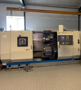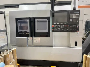
Technical Buyer’s Handbook: Assessing Pre-Owned , Used , Secondhand, Surplus CNC Machines Before Purchase Okuma GENOS L300-M-e CNC Turning Center with Edge Technologies Rebel V-80 Bar Feeder made in Japan
Here is a Technical Buyer’s / Due-Diligence Handbook for assessing a Okuma GENOS L300-M-e CNC turning center combined with an Edge Technologies Rebel V-80 bar feeder (Japan origin for Okuma, U.S. for Edge) before purchase. Use it as a guide; you should tailor tolerances, weightings, and methods for your shop’s precision requirements, materials, and throughput targets.
I. Benchmark / Reference Specifications
II. Pre-Inspection / Remote Preparation
III. Structural / Static Inspection (Power-Off)
IV. Power-Up & Dynamic / Functional Testing
V. Precision, Accuracy & Calibration Tests
VI. Bar Feeder (Rebel V-80) Specific Checks
VII. Documentation & History Review
VIII. Risk Assessment & Cost Forecasting
IX. Contractual Safeguards & Clauses
X. Post-Delivery / Commissioning Checklist
I. Benchmark / Reference Specifications
Before arriving, gather or confirm the machine’s actual spec sheet (serial number, options). Below are typical published / catalog specs for a Genos L300 (or L300 variant) and Rebel V-80 to serve as target ranges.
| Component | Parameter | Typical / Published Value |
|---|---|---|
| Okuma GENOS L300 (or L300-series) | Maximum turning diameter | ~ Ø 340 mm (≈ 13.39″) |
| Maximum turning length | ~ 500 mm (≈ 19.69″) | |
| Spindle speed range | 38 – 3,800 rpm | |
| Spindle power (20 min) | 22 kW (≈ 30 hp) | |
| Rapid traverse (X / Z) | ~ 25 / 30 m/min | |
| Turret, driven tools, optional features | Varies depending on model options | |
| Edge Rebel V-80 Bar Feeder | Bar diameter capacity | 8 mm to 80 mm (0.315″ – 3.150″) |
| Maximum bar length | 60″ (≈ 1,524 mm), constrained by spindle length | |
| Magazine rack capacity | ~ 711–762 mm (28–30″) | |
| Cycle / loading time | ~ 20 seconds (bar load cycle) | |
| Footprint / weight | 84″ × 48″; ~1,100 lbs (~500 kg) |
These specs are intended as reference — real units may differ due to options, wear, or modifications. Use these to detect excessive deviation during inspection.
II. Pre-Inspection / Remote Preparation
Before visiting the seller site, gather as much documentation, photos, and preliminary data as possible. This reduces surprises and helps you prepare your inspection tools.
- Request documentation / files
- Mechanical, electrical, hydraulic, and control (CNC) manuals
- Wiring diagrams, I/O maps, control logic, interface schematics
- CNC parameter backups, compensation tables, offset data
- Maintenance / repair logs (spindle rebuilds, axis rebuilds, turret issues)
- Calibration / alignment / geometric inspection certificates
- Retrofit / option history (driven tools, live tooling, high-speed spindle, coolant-through-spindle)
- Spare parts list, tooling, fixtures included
- Photos & videos: overall machine, spindle, turret, axes, tool magazine, control cabinet, wiring runs
- Motion video or remote demonstration (axis jogs, tool changes, spindle run) - Key questions to the seller
- Year of manufacture, serial number
- Total machine / spindle hours
- Operating material history (steel, aluminum, casting, etc.)
- Reason for sale / decommission
- Known faults, collisions, accidents, repair history
- Which options / features are installed (Y-axis, driven tools, live tooling, coolant-through-spindle, etc.)
- CNC controller make / version, backup of parameters
- Is the machine currently operational or decommissioned? - Prepare tools & metrology equipment
- Dial indicators, test bars, precision squares, straight edges
- Micrometers, calipers, gauge blocks
- Laser interferometer or alignment system (if available)
- Vibration / accelerometer sensor
- IR / thermography camera
- Tools for opening cabinets, measuring continuity, wiring inspection - Logistics / site assessment
- Machine weight, footprint, rigging / crane access
- Foundation / floor load rating, leveling possibilities
- Power supply (voltage, phase, capacity)
- Coolant / chip removal systems, filtration, exhaust
- Clearance for access, maintenance, door width
III. Structural / Static Inspection (Power-Off)
On arrival, before powering, conduct a methodical structural and mechanical inspection.
A. Frame, Base, Castings
- Inspect the base, bed, column, supports, and casting for cracks, weld repairs, distortion, or evidence of overload.
- Look for signs of foundation re-shimming or leveling corrections.
- Check for corrosion, pitting, coolant damage, wear in chip / splash zones.
- Examine covers, way covers, bellows, seals, guards for missing or damaged parts.
- Use long straight edges, reference gauges or precision bars to detect gross warpage or twist in structural members.
B. Linear Axes, Guideways, Carriages & Screws
- Inspect guide rails / blocks for scoring, pitting, spalling, wear marks.
- Check carriage blocks / slides for side play, looseness, binding.
- Examine ball screws / lead screws, nuts, couplings for backlash, wear, thread damage.
- Manually (if safe) move axes to feel for stick-slip, friction zones, binding.
- Check lubrication / grease / oil systems: lines, fittings, leaks, contamination.
C. Turret / Tooling System
- Inspect turret indexing mechanism: gear teeth, locking surfaces, backlash.
- Tool holder clamp surfaces, grippers, collets, and tool change arms for wear or damage.
- Check sensors, limit switches, mechanical travel stops, alignment.
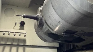
D. Spindle / Head
- Inspect spindle nose, taper, clamping surfaces for wear, burrs, damage.
- Check the spindle housing, seals, coolant / oil leakage.
- If possible, insert a test bar (non-driven) to check static run-out.
- Inspect coupling and support structure around spindle.
E. Electrical / Control Cabinets & Wiring
- Open cabinets (if allowed) and inspect wires, terminal blocks, connectors.
- Look for signs of heating: discolored insulation, melted wires.
- Inspect drive modules, control boards, I/O modules for dust, damage, corrosion.
- Check fans, filters, ventilation.
- Inspect cable carriers, moving cables for abrasion or failure.
F. Safety Interlocks, Limit / Home Switches, E-stop
- Confirm Emergency Stop (E-stop) buttons are present and mechanically intact.
- Inspect guard doors, interlock sensors, safety covers.
- Check limit / home / reference switches on all axes, confirm wiring integrity.
- Watch for bypass wiring circumventing safety circuits.
IV. Power-Up & Dynamic / Functional Testing
Once static checks are acceptable and safety assured, power up and perform functional and dynamic tests.
1. Control & Startup Diagnostics
- Power the CNC / control; observe boot messages, alarms, error logs.
- Confirm parameters, compensation tables, offsets load correctly.
- Check I/O: limit / home / safety switches, feedback sensors, interlocks.
- Jog axes slowly at low feed; observe motion smoothness, correct direction, no binding.
2. Homing / Reference / Return Moves
- Execute reference / homing cycles for X, Z (and any auxiliary axes).
- Repeat multiple times to measure consistency of reference position (repeatability).
- Trigger limit switches to confirm safe stops or retraction behavior.
3. Axis Motion & Positioning
- Move axes over full (safe) travel to feel smoothness, detect changes in friction.
- Command precise incremental moves (e.g., 100 mm, 50 mm) and measure via dial indicator or metrology device to verify actual vs commanded movement.
- Reverse direction and test for backlash or dead zone.
- Perform simultaneous axis motion (if control supports) to test coordination (e.g. X + Z).
4. Turret / Tool Change / Indexing
- Cycle turret tool changes many times, monitoring indexing speed, smoothness, positional consistency.
- Try different tool lengths / diameters (within safe limits) to test flexibility.
- Check sensors, grippers, locking mechanism reliability.
5. Spindle Performance / Turning Test
- Run spindle at low rpm, gradually increase; listen for vibration, noise, resonance.
- If possible, mount a test workpiece / test bar to measure dynamic run-out.
- Monitor spindle motor current, thermal stability, fluctuation.
- Under light cut, examine behavior, chatter, consistency.
6. Sample Machining Run
- Program a light turning operation (e.g. facing, turning) on aluminum or mild steel.
- Compare resulting geometry to programmed geometry; check surface finish, dimension.
- Run multiple cycles to observe repeatability and drift over time.
- Monitor vibration, load spikes, anomalies during cutting.
7. Safety / Fault / Interlock Tests
- Press E-stop mid-motion / cutting / tool change; verify machine stops safely.
- Trigger limit switches prematurely to test axis safe response.
- Open guard doors during safe mode; confirm HV / motion disable.
- Simulate sensor or feedback failure (if safe) and observe error handling path.
8. Thermal / Drift / Stability Test
- Run axes or idle mode for 30–60 minutes to allow thermal stabilization.
- After warm-up, re-test critical positions, backlash, repeatability to detect drift.
- Monitor motor, drive, control cabinet, spindle, turret temperatures.
- Use IR / thermography or vibration sensors to spot hotspots or marginal components.
V. Precision, Accuracy & Calibration Tests
Once thermally stable, conduct detailed precision tests.
- Repeatability: Move to a point, retract, return, measure deviation (multiple cycles).
- Grid / mapping test: Command a grid of coordinate positions across travel and measure deviations to map error fields.
- Linearity / scale calibration check: Use calibrated gauge sticks or laser interferometer if available.
- Backlash / hysteresis checks: move back and forth in each axis and measure variance.
- Turret / tool offset calibration: check that each tool position is consistent and offsets correctly.
- Stiffness / deflection test: apply load (e.g. test cut or offset part) and measure deflection or deviation.
- Compare measured deviations vs your acceptable tolerances or original OEM specs.
VI. Bar Feeder (Edge Rebel V-80) Specific Checks
Since your configuration includes a bar feeder, you must inspect it carefully.
- Alignment & Mounting
- Verify centerline alignment to lathe spindle bore—bar feed must match lathe centerline precisely.
- Check base / anchors, leveling, and rigidity of mounting.
- Ensure the axial track / shift mechanism (if present) operates smoothly. - Magazine & Bar Handling
- Inspect magazine for wear, roller guides, fingers, separators.
- Confirm proper gripper / finger action, no binding, proper clearances.
- Check the V-tray raising/lowering mechanism, load / unload sequence.
- Ensure the magazine capacity, incline, and rail alignment match specs (e.g. 711–762 mm rack capacity) - Drive, Motors & Controls
- Check servo drives, motors, cables, connectors, interface to lathe.
- Verify the feeder’s control / PLC logic and correct interlocks / safety circuits.
- Jog / test pushers, V-tray motion, load & retract sequences. - Cycle / Timing Tests
- Run a bar change / feed cycle; measure cycle time, detect stalling, misfeed.
- Load / unload repeated cycles to test reliability.
- Check behavior with bar of min / max diameters and close tolerances. - Safety / Interlock Checks
- Ensure feeder interlock signals tie correctly into lathe control (bar on, bar feed enable, etc.).
- Verify emergency stop / sensor failure behavior.
- Confirm mechanical safety stops and limit switches function. - Wear / Maintenance
- Inspect sliding components, guide rails, lubricant points, belts.
- Check for worn or loose parts, replacement options.
VII. Documentation & History Review
When dynamic and precision testing are done, scrutinize the documentation and past history.
- Maintenance / repair logs: spindle rebuilds, turret repairs, axis overhauls
- Calibration / alignment & error compensation certificates
- Retrofit history: bar feeder addition, control upgrades, spindle upgrades
- CNC / controller software versions, backup parameter files
- Records of service parts replacement
- Included spare parts, tooling, fixture packages
- Original warranty or support availability (if any)
VIII. Risk Assessment & Cost Forecasting
Using your inspection data, build a risk / cost model to decide what you are willing to pay, what to reserve for refurbishment, and contingency.
- High-wear or high-risk subsystems: spindle bearings, turret, guideways, bar feeder moving parts
- Spare part availability & lead times (Okuma, Edge feeder parts)
- Alignment / calibration / compensation cost post-move
- Reconditioning costs of worn components
- Transport / handling risk (shock, misalignment, component damage)
- Commissioning / tuning / debug downtime
- Obsolescence for control electronics, servo drives
- Salvage value of structural parts
You can create a scoring matrix (e.g. structure, axes, spindle, turret, feeder, control) to rate candidate machines and set your maximum offer margin.
IX. Contractual Safeguards & Purchase Clauses
From your due diligence, negotiate protective clauses into your purchase agreement.
- Acceptance / on-site test clause: final payment contingent on passing all functional, dynamic, and precision tests after installation.
- Price adjustment / penalty clause: allow deductions if key metrics (repeatability, run-out, feeder performance) deviate beyond agreed thresholds.
- Warranty / latent defect clause: cover hidden defects (e.g. spindle faults, drive failures) for a set period (e.g. 3–6 months).
- Spare parts & tooling inclusion: require key wear parts for turret, spindle, feeder, guides included.
- Documentation / data handover: require delivery of manuals, wiring diagrams, CNC parameter backups, calibration / alignment records.
- Transport / insurance clause: clearly assign liability for damage during shipping, unloading, installation.
- Commissioning / support clause: require seller or OEM technician support during first alignment, calibration, and setup.
X. Post-Delivery / Installation & Commissioning Checklist
After you receive and install the machine, perform a disciplined commissioning sequence.
- Prepare foundation, level machine, anchor, establish rigidity
- Clean, flush lubrication, coolant, hydraulic systems; replace filters / fluid
- Reconnect and verify wiring, grounding, safety interlocks
- Power up and repeat full acceptance / dynamic / precision test suite
- Perform full alignment, calibration, compensation mapping
- Run sample parts in your actual materials and programs; verify geometry, surface finish, repeatability
- Record baseline performance metrics (repeatability, drift, backlash, thermal behavior)
- Train operators and maintenance staff (especially feeder operation, integration)
- Establish preventive maintenance schedule (turret checks, spindle inspection, feeder maintenance)
- Monitor performance closely for first weeks to detect drift, anomalies, error logs