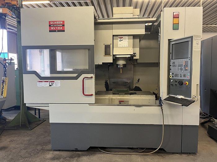
Technical Buyer’s Handbook: Assessing Pre-Owned , Used , Secondhand, Surplus CNC Machines Before Purchase Quaser MV 184E CNC Vertical Machining Center made in Taiwan
Below is a Technical Buyer’s Handbook / Inspection & Assessment Guide customized for a Quaser MV 184E (or MV184 / MV184 Series) CNC Vertical Machining Center (made in Taiwan). Use it as a structured checklist and adapt tolerance thresholds and tests to your accuracy requirements, material types, and production volumes.
I also include benchmark specs from public sources (Quaser’s catalog, used listings) to guide what “normal” performance should look like.
0. Reference / Benchmark Specifications (Quaser MV 184 / MV184E)
These parameters serve as your expected target ranges. If the machine you inspect is significantly worse, you’ll need to discount or understand why (wear, retrofit, damage).
From Quaser catalog / used-machine data:
| Spec | Value / Range | Notes / Sources |
|---|---|---|
| X-axis travel | 1,020 mm (~ 40.2″) | |
| Y-axis travel | 610 mm (~ 24″) | |
| Z-axis travel | 610 mm (~ 24″) | |
| Table size | 1,200 × 600 mm | |
| Table load / workpiece capacity | 500 kg | |
| Spindle taper / tool holder | BT40 (or ISO 40) | |
| Maximum spindle speed | ~ 12,000 rpm (some units) | |
| Tool magazine capacity | 30 tools standard | |
| Max tool diameter (free adjacent) | 76 mm (when neighbor pots empty up to ~125 mm) | |
| Max tool length | ~ 280 mm | |
| Machine weight / footprint | ~ 7,090 kg / dimensions ~ 3,340 × 2,920 × 2,860 mm (for a 2014 unit) | |
| Rapid feeds / traverse | X/Y: ~ 40 m/min, Z: ~ 36 m/min |
Note: Some variants (e.g. MV184E) may support higher spindle rpm, coolant-through-spindle, or other options—verify based on the specific machine you inspect.
Use these specs as your “reference envelope.” Any candidate machine that deviates substantially (e.g. a spindle limited to 6,000 rpm, or very worn axes) must be discounted or inspected more deeply.
I. Pre-Inspection / Remote Preparation
Before going to inspect, gather as much information, photos, and documentation as possible.
Documents / Data to request:
- Mechanical, electrical, control (CNC) manuals, wiring diagrams, I/O maps
- CNC parameter backups, compensation tables, offset files
- Maintenance / repair records: spindle rebuilds, guide replacements, overhaul history
- Calibration / geometric inspection reports
- Option / retrofit history: coolant-through-spindle (CTS), high rpm spindle, special tooling, control upgrades
- Spare parts lists, tooling, fixtures, collets, pull studs
- High-resolution photos / videos: overall machine, table, spindle, axes, interior cabinets, wiring
- If possible, video demonstration: axis jogging, tool changes, spindle run
Questions to ask the seller:
- Year of manufacture, serial number
- Total operating hours / spindle hours
- History of load usage (materials, heavy cuts, mold work)
- Reason for sale / decommission
- Known faults, damage, collisions, past repairs
- Which options / features are installed (CTS, high rpm, tool probe, linear scales, etc.)
- CNC control type and version
- Is the machine currently operational / powered or disassembled?
Bring / Prepare Inspection Tools:
- Dial indicators, test bars, precision straight edges, squares
- Micrometers, gauge blocks
- Laser interferometer / alignment gear (if possible)
- Vibration sensor / accelerometer
- IR / thermography camera
- Tools to open panels, measure wiring continuity, check drives
Site / Logistics Pre-check:
- Machine weight, rigging / crane requirements
- Floor / foundation load capacity, need for leveling / anchor bolting
- Power supply (voltage, phases, available current)
- Coolant, chip handling, exhaust / filtration systems
- Clearance around the machine for service and access
II. Structural / Static Inspection (Power-Off)
When you arrive, carefully perform a mechanical walk-around, focusing on structural / wear components before powering anything.
1. Frame, Base, Castings & Structure
- Inspect the bed, base, columns, casting surfaces for cracks, repaired welds, distortion or visible shifts.
- Look for signs of re-leveling, excessive shimming, or foundation repairs.
- Examine corrosion, coolant / chip damage, pitting especially around splash / chip zones.
- Check way covers, bellows, guards, seals for missing or damaged parts.
- Use long straight edges, gauge bars or surface plates to spot gross twist or bending of key structural elements.
2. Guideways, Linear Axes & Carriages
- Inspect linear guide rails / slides for wear marks, pitting, spalls, edge chipping.
- Check carriages / blocks for looseness, side play, binding.
- Inspect ball screws / drive screws, nuts, couplings for backlash, wear, thread damage.
- Manually move axes (if safe) across travel to feel for binding zones, uneven friction.
- Check lubrication / oil lines, fittings, look for leaks, contamination, clogged lines.
3. Spindle / Head / Tool Interface
- Examine spindle nose, taper, clamping surfaces, interface for wear, scoring, burrs.
- Check spindle housing, seals, cooling lines, lubricants, for leakage or deterioration.
- If possible, insert a test bar (non-driven) to check for static run-out / eccentricity.
- Inspect coupling and bearing support around spindle for mechanical integrity.
4. Tool Changer / Magazine
- Inspect magazine pockets, indexing mechanism, arms, slides, and grippers.
- Check mechanical linkages, bearings, sensors, limit switches.
- Check for wear, misalignment, play in the tool-change mechanism.
- Cycle the ATC (if safe) to visually observe motion smoothness.
5. Electrical / Control Cabinets & Wiring
- Open cabinets (if granted) and inspect wiring, terminal blocks, connectors.
- Look for discoloration, melted insulation, signs of overheating.
- Examine drive modules, I/O boards, control boards for dust accumulation, damage.
- Check ventilation / fan / filter paths.
- Inspect cable carriers, moving cables, drag chains for wear or abrasion.
6. Safety / Interlocks, Limit & Home Switches
- Verify presence and mechanical integrity of Emergency Stop (E-stop) buttons.
- Examine guard doors, interlock switches, and wiring.
- Check limit / home / reference switches on each axis.
- Ensure no bypass wiring or disabled safety circuits.
III. Power-Up & Dynamic / Functional Testing
After structural inspection, if conditions permit and safety is assured, power up and perform functional tests.
1. Control Startup & Diagnostics
- Power on the CNC / control, observe boot messages, alarms or error conditions.
- Check that parameter backups, compensation tables, offset maps load properly.
- Confirm I/O status for limit / home / safety interlocks, sensors.
- Jog axes at low speed; verify direction, smoothness, no stiction or binding.
2. Homing / Reference Moves & Repeatability
- Execute homing / reference cycles for X, Y, Z axes.
- Repeat homing multiple times and measure consistency / repeatability of reference position.
- Trigger limit switches to validate safe stops / axis retraction behavior.
3. Axis Motion & Accuracy Checks
- Traverse axes across safe travel range; observe for uneven friction, jerky motion.
- Command precise incremental moves (e.g. 100 mm) and measure with dial gauge or metrology tool.
- Reverse direction and check for backlash or hysteresis.
- Execute combined axis moves (if control supports) to assess multi-axis synergy.
4. Spindle Performance & Load Test
- Start spindle at low rpm and ramp gradually; listen and feel for vibration, anomalies.
- Mount test workpiece or tool and perform light machining cut to test under load.
- Monitor spindle motor current, torque behavior, thermal stability.
- Observe behavior under continuous operation to detect drift or degradation.
5. Tool Change / ATC Cycling
- Cycle tool changes repeatedly; monitor timing, consistency, sensor feedback.
- Use various tool sizes / lengths to test flexibility.
- Watch for mis-indexing, gripper issues, slow cycles, or collisions.
6. Machining / Sample Workpiece Test
- Run a test milling job (e.g. slotting, face milling) in a material representative of your production.
- Measure part geometry vs programmed path, check surface finish and tolerances.
- Run multiple cycles to observe drift, thermal shift, repeatability.
- Monitor for vibration, load anomalies, tool deflection.
7. Safety / Fault Handling Tests
- Engage E-stop during axis motion, spindle run, tool change – machine should stop cleanly.
- Trigger limit switches or out-of-range moves to test safe error behavior.
- Open guard doors during idle / safe mode to test interlock response.
- Simulate sensor feedback loss (if safe) to see how error recovery works.
8. Warm-Up / Drift / Stability Test
- Let the machine run idle or traverse for 30–60 minutes to reach thermal steady state.
- After warm-up, retest key motions, backlash, repeatability to detect drift.
- Monitor temperatures of motors, control cabinet, spindle area, axes.
- Use IR / thermography or vibration sensors to find hotspots or failing components.
IV. Precision, Calibration & Accuracy Validation
Once the machine is thermally stabilized, do precision-level inspections to evaluate its usable accuracy envelope.
- Repeatability test: move to a point, retract, return, measure deviation over multiple cycles.
- Grid / mapping test: command a mesh of points across the working envelope, measure positioning deviation, and plot error maps.
- Linearity / scale calibration check: use calibration sticks or a laser system if available.
- Backlash / hysteresis checks: sweep back-and-forth movements, compare deviations.
- Tool offset / compensation evaluation: test tool offsets & whether the control compensates properly.
- Under load or at extremes, test for deflection / compliance.
- Compare measured results with allowable tolerances (based on your production specs or original OEM data).
V. Documentation & Maintenance / Service History Review
After mechanical and dynamic testing, evaluate all documentation and background:
- Maintenance / repair logs: spindle rebuilds, guide replacements, major repairs
- Calibration / alignment / geometry inspection certificates
- Retrofit / upgrade history: high rpm spindles, CTS, probe systems, control upgrades
- CNC control versions, software backups, parameter files
- Spare parts inventory (bearings, screws, encoders, tooling)
- Tooling, fixtures, included accessories
VI. Risk Assessment & Life-Remaining Estimate
Using your inspection data, build a risk model and cost forecast:
- High-wear subsystems: linear guides, ball screws, spindle bearings, ATC mechanism
- Availability / cost of spare parts for Quaser / Taiwanese machines
- Calibration / alignment / compensation cost post-move
- Reconditioning costs (bearings, seals, guide restoration)
- Transport / installation risks (shock, alignment shifts, structural stress)
- Commissioning / tuning / debug downtime
- Control electronics obsolescence risk
- Salvage / fallback value of structure if machine fails
You can create a scoring matrix (structure, axes, spindle, tooling, control) to compare candidates and set maximum bid or repair reserve budget.
VII. Contractual Safeguards & Negotiation Clauses
Leverage your inspection findings to include protective clauses:
- Acceptance / test-out clause: sale is conditional on passing your precision, functional, and dynamic tests after installation
- Price adjustment clause: permit deduction or seller compensation if key metrics deviate beyond agreed thresholds
- Warranty / latent defect clause: cover hidden defects (spindle, guide, drives) for a defined period (e.g. 3–6 months)
- Spare parts / tooling inclusion: require key wear parts and tooling / fixtures included
- Documentation clause: ensure delivery of manuals, wiring, CNC backups, alignment / calibration data
- Transport / insurance clause: specify responsibility for damage during shipping, handling, unloading
- Commissioning / support clause: require seller / OEM technician to assist setup, calibration, alignment
VIII. Post-Delivery / Installation & Commissioning Checklist
After the machine arrives and is installed, execute a systematic commissioning and acceptance process:
- Level, anchor, and align foundation / base / structure
- Clean, flush lubrication, coolant, chip removal systems; replace filters / fluids
- Reconnect safety circuits, guards, wiring, grounding
- Power-up and re-run your full acceptance / dynamic / precision test suite
- Perform alignment, calibration, compensation mapping, error correction
- Run test parts in production materials to validate performance
- Record baseline metrics (repeatability, drift, backlash, thermal behavior)
- Train operators & maintenance staff on quirks, preventive maintenance, usage
- Set up preventive maintenance schedule (guide checks, spindle checks, calibration intervals)
- Closely monitor performance during early production period for drift, anomalies, error trends