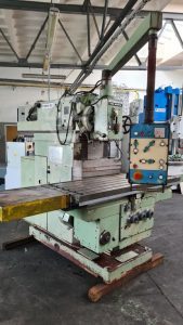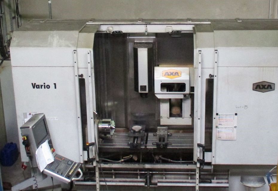
Technical Buyer’s Handbook: Assessing Pre-Owned , Used , Secondhand, Surplus CNC Machines Before Purchase AXA Vario 1 CNC Milling Machine made in Germany
Below is a Technical Buyer’s Handbook / Inspection & Assessment Guide tailored for evaluating a pre-owned / used / surplus AXA Vario 1 CNC milling machine (made in Germany). Use this as a checklist you can adapt by your required tolerances, workpiece sizes, and production demands.
Also included are some benchmark specs gathered from used-machine listings to guide expectation.
0. Benchmark / Reference Specifications (AXA Vario / Similar)
Because “Vario 1” is a less common model name, I used publicly listed “AXA Vario” machines as a baseline for what to expect:
From TP-Machines:
- Model: Vertical machining center, AXA Vario (Germany)
- Year: 2001
- Control: Heidenhain TNC 410
- Table: 2030 × 500 mm, max load ~ 600 kg / 1000 mm
- Travels: X ≈ 1760 mm (2 × 700 mm), Y = 500 mm, Z = 600 mm
- Spindle: 6,000 rpm, 12 kW (40 %)
- Tool magazine: 22 stations, tool taper SK40
- Distance spindle nose to table: 230 – 830 mm
- Machine dimensions: ~ 3.9 × 2.9 × 3 m, weight ~ 9 t
Also, other listings of “AXA Vario” show the same control type (TNC 410) and table sizes ~2030 × 500 mm.
These numbers set your “target window.” If your candidate machine deviates significantly, you’ll need to dig into reasons (wear, modifications, partial retrofits) and discount accordingly.
I. Pre-Inspection / Remote Phase
Before visiting, try to gather as much information and documentation as possible. This reduces surprises and lets you prepare your inspection tools.
Documents / data to request:
- Original / service manuals (mechanical, electrical, control)
- Wiring schematics, I/O maps, CNC parameter / compensation files
- Maintenance & repair logs (spindle rebuilds, linear guide replacement, major repairs)
- Calibration, alignment, geometric inspection certificates
- History of modifications or retrofits (e.g. spindle upgrade, control swap)
- Spare parts list / BOM, tooling list
- Photos of machine (overall, axes, table, spindle, control cabinet, wiring)
- Videos / remote demo of axis motions, spindle run, tool changes
Key questions to ask the seller:
- Year of manufacture, serial number
- Total hours (machining hours, spindle hours)
- Reason for sale / decommission
- Known faults, collisions, damage history
- What options / extras are installed (e.g. probing, coolant through spindle, direct measuring)
- Whether the machine is currently functional or disassembled
- What tooling / fixtures / probes are included
Prepare / bring inspection instruments:
- Dial indicator, test bar, precision squares, straight edges
- Laser interferometer or alignment tools (if possible)
- Vibration sensor / accelerometer
- Thermography / IR camera
- Feeler gauges, micrometers
- Tools to open covers, measure wiring continuity, etc.
Check logistical / site constraints:
- Machine weight, dimensional footprint, rigging / crane access
- Floor strength, foundation, leveling adjustments
- Power supply (voltage, phases, capacity)
- Cooling / lubrication systems, air, exhaust, chip removal
- Space clearance around the machine
II. Visual & Static / Structural Inspection (Power-Off)
Once on site, before powering, carefully walk around and inspect all structural, mechanical, and visible subsystems.
1. Frame, Base, Structure
- Inspect the frame, machine base, columns, and casting for cracks, weld repairs, distortion, or signs of stress.
- Look for evidence of re-shimming, foundation settling, or repair patches.
- Check for corrosion, pitting, especially in coolant/ chip splash zones.
- Examine covers, guards, way covers, bellows, seals: missing, damaged, misaligned parts.
- Use straight edges or long gauges to check gross machine alignment / twist.
2. Guideways, Linear Slides & Ball Screws
- Inspect linear guide surfaces (rails, blocks) for wear marks, pitting, spalling, scoring.
- Check carriage / block play: side play, looseness, lateral movement.
- Inspect ball screws / lead screws, nuts, couplings for backlash, wear, binding.
- Manually (if safe) push / slide axes to detect friction, variation, binding spots.
- Inspect lubrication / grease / oil circuits: blocked lines, leaks, contamination.
3. Spindle, Spindle Head & Tool Interface
- Inspect spindle nose, taper, thread surfaces for wear, chips, damage.
- Check spindle housing for discoloration, signs of overheating or lubricant leakage.
- If possible, insert a test bar (non-driven) to check static run-out.
- Inspect cooling / lubrication circuits to the spindle, verify seals, hoses.
4. Tool Magazine / Tool Changer (if present)
- Inspect magazine pockets, indexing mechanism, carousels for wear, misalignment.
- Examine arm mechanisms, grippers, slides, actuators.
- Check sensors, limit switches, connectors, wiring for damage or misalignment.
5. Electrical Cabinet, Drives, Wiring
- Open control / drive cabinets (if permitted) and inspect wiring, connectors, terminal blocks.
- Look for heat damage (discolored insulation, melted parts), loose wiring.
- Check the condition of drive modules, control boards, I/O modules.
- Inspect cooling fans, filters, ventilation paths, dust accumulation.
- Check cable carriers / drag chains, motion cables for wear or breakage.
6. Safety Interlocks, Guards, Limit / Home Switches
- Confirm the presence and mechanical integrity of Emergency Stop (E-stop) buttons.
- Inspect guard doors, safety interlock switches.
- Verify limit / home switches on each axis for presence and physical condition.
- Ensure no obvious bypass or override wiring is in place.
III. Power-Up & Dynamic / Functional Testing
Once structural inspection is acceptable and safety is assured, carefully power up and test dynamic functions.
1. Control & Diagnostics
- Power the control / CNC, observe boot sequence, alarms, error logs.
- Check that parameters, offset tables, compensation maps load correctly.
- Test I/O: confirm limit / home / safety inputs are read correctly.
- Jog each axis slowly, check motion smoothness, direction correctness, no binding.
2. Homing / Reference / Zeroing Cycles
- Execute homing / referencing cycles for the X, Y, Z axes (and any auxiliary axes).
- Repeat homing several times; measure repeatability of return home position.
- Trigger soft / hard limits (safely) to verify axis limits behave correctly.
3. Axis Traversal & Motion Behavior
- Move axes over full safe travel at moderate speed; listen/feel for jerk, friction, irregular movement.
- Command precise moves (e.g. 100 mm, 200 mm) and measure actual movement using dial indicator or laser.
- Reverse direction and measure backlash / play.
- Run diagonal / multi-axis motions (if control supports) to test coordination.
4. Spindle / Rotational Test
- Run spindle at low rpm and ramp up, observe for vibration, noise, run-out.
- If possible, mount a test workpiece / test bar and measure dynamic run-out.
- Monitor motor current, temperature stability, fluctuations.
- Check spindle cooling / lubrication under operational conditions.
5. Tool Change / ATC (if present) Testing
- Perform multiple tool change cycles; monitor timing, sensor detection, cyclic consistency.
- Cycle the tool changer many times to spot intermittent issues.
- Use different tools (lengths, diameters) within safe limits to test flexibility.
6. Machining Test / Sample Operation (If Permissible)
- Program a simple test cut (e.g. light milling on aluminum) to simulate actual operation.
- Measure resulting geometry vs programmed path, examine surface finish.
- Operate continuous cycles to detect drift, thermal deformation.
- Monitor vibrations, power draw, anomalies over time during machining.
7. Safety / Fault Behavior Tests
- Trigger E-stop mid-motion / spindle operation; machine should stop safely.
- Activate limit switches / sensor faults; check whether axes retract or stop cleanly.
- Simulate sensor or input faults (if safe) and evaluate error handling behavior.
- Open guard doors during motion (if possible under safety constraints) to test interlock.
8. Stability / Endurance / Drift Tests
- Run axes motion or idle periods for a significant duration (30–60 min) to allow thermal stabilization.
- After warm-up, re-measure key motion points, backlash, repeatability to detect drift.
- Monitor temperatures of motors, drives, controller cabinet, spindle.
- Use thermography or vibration sensors to spot overheating or resonance.
IV. Precision, Calibration & Accuracy Verification
With machine warmed up and stable, carry out precision tests to verify suitability for your tolerance requirements.
- Repeatability test: move to a fixed point, retract, return, measure variation.
- Mesh / grid positioning test: command a sequence of XY / XYZ positions and measure deviations across the workspace.
- Squareness / orthogonality checks: e.g. move in X then Y vs Y then X, compare result.
- Spindle alignment / overlay: check that spindle centerline remains consistent across motion.
- Under load / offset part positions, check for deflection or deviation due to mass or lever arms.
- If available, use laser interferometer, calibration bars, and proper metrology equipment.
- Compare measured errors vs acceptable tolerances (based on your parts requirement or spec sheet).
V. Documentation & Maintenance / Service History Review
After functional and precision testing, thoroughly review all documentation and background.
- Maintenance & repair logs: spindle overhauls, guide replacements, major repairs
- Calibration / alignment certificates
- Retrofitting or upgrade history
- CNC / software version / backup files
- Spare parts inventory (bearings, guides, spindle components, control modules)
- Tooling, fixtures, accessories included
VI. Risk Assessment, Remaining Life Estimation & Cost Forecasting
Using your inspection results, build a risk and cost model.
- Identify high-wear subsystems: linear guides, ball screws, spindle bearings, tool changer mechanisms.
- Assess spare parts availability / lead times, especially AXA / German machine tool parts.
- Estimate cost for calibration, re-alignment, compensation tuning after transport.
- Budget for reconditioning of key components.
- Consider transport / installation risks (shock, alignment shift, component damage).
- Estimate commissioning downtime and ramp-to-quality cost.
- Evaluate control / electronics obsolescence risks.
- Evaluate salvage / fallback value of structural parts if machine fails.
You may build a weighted scoring matrix (structure, axes, spindle, tooling, control) so you can quantify condition and set your maximum acceptable purchase price or repair buffer.
VII. Contractual Safeguards & Negotiation Clauses
Based on your inspection leverage, include protective provisions in your purchase contract.
- Acceptance / test-out clause: final purchase is contingent on passing your functional and precision tests after installation.
- Price adjustment / deduction clause: allow deduction if deviations exceed agreed limits.
- Warranty / latent defect clause: e.g. 3–6 months for hidden failures (spindle, control, drives).
- Spare parts / tooling package clause: require key components (guides, screws, electronic modules) included.
- Documentation delivery clause: manuals, wiring diagrams, CNC backups, alignment / calibration data must be handed over.
- Transport / insurance clause: clearly specify liability for damage during shipping / unloading / installation.
- Commissioning / support clause: require seller or OEM technician support during first alignment / calibration.
VIII. Post-Purchase / Installation & Commissioning Checklist
Once the machine is delivered and installed in your facility, go through a disciplined commissioning sequence.
- Prepare foundation, leveling, anchoring, vibration isolation
- Clean, flush and commission lubrication / coolant systems; replace filters / fluids
- Reinstall covers, guards, safety interlocks
- Power-up and repeat your full acceptance / dynamic / precision test suite
- Perform alignment, geometry calibration, error compensation mapping
- Run test parts in your real materials to validate performance under production conditions
- Capture baseline metrics (repeatability, drift, backlash)
- Train operators & maintenance staff on quirks and procedures
- Create preventive maintenance schedule (guide checks, spindle checks, alignment checks)
- Monitor performance for first weeks: drift, anomalies, error logs