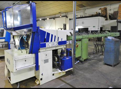
Technical Buyer’s Handbook: Assessing Pre-Owned , Used , Secondhand, Surplus CNC Machines Before Purchase Manhurin KMX 26 made in France
Below is a Technical Buyer’s Handbook / Due-Diligence Checklist for evaluating a pre-owned / used / surplus Manurhin KMX 26 (made in France) CNC machine (likely sliding head / Swiss-type or small lathe style), with special focus on risks, key inspection items, and negotiation leverage.
You should adapt tolerances, required features, and weightings to your own application (e.g. diameter, length, precision, throughput).
I. Background & Reference Specifications
Before inspection, obtain or establish a “healthy / nominal” spec sheet for the machine. For the Manurhin KMX 26, typical published specs (or from used listings) include:
- Year: ~ 1990 in some listings
- Bar capacity / bar diameter: 26 mm
- Spindle speed: 200 – 6,000 rpm
- Spindle power: ~ 5 kW
- Axis count: 3 axes (X, Z, possibly Y or live tooling)
- Turrets: 2 turrets, 6 stations (example listing)
These numbers give you baseline expectations. You should try to acquire the original specification sheet / manual for your exact serial number.
II. Pre-Inspection / Preparation (Desk / Remote Phase)
Before going on site, collect as much as you can:
- Original manuals: mechanical, electrical, control, lubrication, hydraulics / pneumatics
- Wiring diagrams, control parameter backups, axis tuning files
- Maintenance logs: parts replaced, repair history, downtime
- Calibration / alignment certificates
- Modification / retrofit records
- Photos & videos (body, machine internals, drive systems, cabling)
- Questions to ask the seller:
• Why is the machine being sold?
• Is it currently operational?
• Known defects (vibration, stability, control errors)
• Which major components have been replaced (ball screws, guides, spindle bearings)?
• Are tooling, chucks, bar feeders included?
• Control / CNC version and backups
Bring with you precision instruments: dial gauges, micrometers, test bars, straight edges, borescopes, vibration meter, thermography camera, etc.
III. Visual / Structural Inspection (Power-Off / Cold)
Do a thorough walk-around and internal inspection before powering.
1. Machine Structure & Frame
- Inspect bed, carriage, castings, column for cracks, weld repairs, distortion, alignment.
- Check leveling / shim pads, anchoring, signs of foundation rework.
- Inspect covers, guards, way covers, bellows, wipers, sliding doors, seals.
- Chip conveyor, coolant tank, coolant piping, and filter system (if present) for leaks, blockages, corrosion.
2. Linear Axes & Motion Components
- Inspect guideways, rails, sliding surfaces for scoring, wear, rust.
- Examine ball screws, nuts, leadscrews for pitting, wear, backlash.
- Check lubrication lines, greasing systems, that they are intact and not clogged.
- Check anti‐backlash devices, preload state, nuts.
- Manually move axes (if permitted) to detect binding, dead zones, uneven motion.
3. Spindle & Tooling
- Inspect spindle nose, taper, threads, clamping surfaces, condition of seating areas.
- Check for discoloration, burned or overheated surfaces.
- If possible, insert test bar or dummy and check static run-out.
- Inspect spindle lubrication, oil circuits, seals, oil leaks.
- Check motor coupling, alignment to spindle.
4. Turrets / Tool Carriers / Live Tools (if any)
- Inspect turret bodies, indexing mechanisms, gear teeth, wear on slides.
- Check grippers/tool holders, clamping arms, sensor systems.
- Check actuation systems (hydraulic, pneumatic, servo) for leaks, wear, response.
- Inspect cabling to live tools, wire routing, shielding, connectors.
5. Electrical & Control Cabinets
- Open cabinets (if allowed) to inspect drives, power modules, I/O racks, controllers, wiring.
- Look for signs of overheating: burnt wires, discoloration, melted insulation.
- Inspect wiring bundles, connectors, cable strain reliefs, terminal blocks.
- Check cooling fans, filters, airflow, ventilation.
- Inspect servo drives, inverters, power supplies, DC bus capacitors (bulging, leakage).
- Check cable carriers / drag chains along moving axes for abrasion, fatigue.
6. Safety & Interlocks
- Confirm presence and condition of emergency stop (E-stop) buttons.
- Verify safety door interlocks, limit switches.
- Ensure guards are present, not bypassed, and functionally intact.
- Interlocks between spindles, turret motion, tool change sequences.
IV. Power-Up & Functional Testing (Under Controlled Conditions)
With safety precautions and possible assistance from seller, proceed to dynamic tests.
1. Control & Diagnostics
- Power up control, observe boot sequence, error logs, alarms.
- Verify parameter memory, backups, calibration data are intact.
- Check I/O status, limit switches, home switches.
- Jog axes at low speed: check smoothness, direction, no unexpected noise.
2. Homing / Referencing Cycles
- Execute homing on all axes (X, Z, possibly Y).
- Repeat homing multiple times; verify repeatability of home positions.
- Test limit switches and soft/hard limit boundaries.
3. Axis Travel & Motion Tests
- Move axes throughout allowable travel at moderate speeds, observe for binding, jerks.
- Command distances (e.g. 10 mm, 100 mm) and measure with dial gauge or reference.
- Reverse direction and measure backlash / dead zone.
- If possible, use ball-bar or other precision test to assess linearity, straightness.
4. Spindle Running
- Start spindle at low rpm, gradually ramp up; monitor for vibration, noise, abnormal behavior.
- Use a test bar to measure dynamic run-out while spinning.
- Monitor spindle motor current, torque behavior, stability.
- Verify cooling / lubrication flow under rotation.
5. Turret / Tool Change & Live Tool Testing
- Command tool changes: observe timing, motion, sensor feedback, any misalignments or crashes.
- Cycle tool changes multiple times to test repeatability & reliability.
- If machine has live tools or driven tools, command them under light load and verify function, smoothness, feedback.
6. Test Cuts / Machining Simulation (if safe and allowed)
- Run a light cut (soft material) to simulate real operations.
- Measure resulting part dimensions vs program, check surface finish.
- Run over an extended time (30-60 min) to see thermal drift or accuracy degradation.
- Monitor vibration, current draw, stability.
7. Safety & Fault Tests
- Trigger E-stop in various states (idle, axis motion, spindle) to ensure safe halting.
- Hit limit switches to confirm stop or reversal.
- Simulate sensor faults or interrupts to check error recovery.
- Verify guards, motion interlocks during operation.
8. Extended Run / Stability / Drift
- Run machine in motion or idle for an extended period to let temperatures stabilize.
- Re-check key positioning, backlash, repeatability for drift.
- Monitor temperatures of drives, motors, spindle, control cabinet.
- Use vibration analysis or thermography to catch heating anomalies or emerging failures.
V. Precision & Accuracy Calibration
Once the machine is stabilized, check how close it operates to required tolerance levels.
- Perform repeatability test: move to a point, return, measure deviation.
- Execute a grid of moves and measure differences to detect linearity, scale errors, angular errors.
- If available, use laser interferometer or ball-bar test equipment for high-precision calibration.
- Test live-tool / driven tool accuracy if present.
- Compare measured error metrics against either factory spec (if available) or your required tolerances.
VI. Documentation & Service History Review
After physical and dynamic tests, thoroughly assess documentation and history.
- Maintenance / repair logs (major repairs, unscheduled downtime)
- Records of parts replaced (ball screws, bearings, spindles, guides)
- Calibration / alignment certificates
- Modifications or retrofits (control upgrades, added axes, sensor changes)
- Control / software version history, backups, licenses
- Spare parts inventory included or not
- Tooling, chucks, support equipment transferred with the machine
VII. Risk Assessment, Life-Remaining & Cost Forecast
From your inspection, build projections and risk models.
- Wear-critical components: spindle bearings, turrets, drive gears, guideways, screws
- Spare parts / support availability: Manurhin support, parts lead times, third-party availability
- Calibration & alignment cost post-move, including expert service
- Transport / reinstallation risk: disassembly, alignment, foundation adjustments
- Downtime & commissioning time until production readiness
- Control / obsolescence risk: CNC modules, drives, electronic parts aging
- Fallback / salvage value: structural, castings, usable parts
You may build a scoring matrix weighting each component (spindle, axes, turret, control, etc.) to derive a risk-adjusted value.
VIII. Contractual Safeguards & Negotiation Terms
Use your inspection findings to insert protections in the contract.
- Acceptance test clause: machine must pass all functional / precision tests after installation
- Price adjustments if performance metrics fall outside agreed tolerances
- Warranty / latent defect clause (e.g. 3 to 6 months)
- Spare parts package: require key wear spares (bearings, seals, coupling, tool changer parts)
- Documentation delivery: full manuals, wiring diagrams, backup files, software
- Transport & insurance: define who is responsible for damage during shipment
- Installation / commissioning aid: seller’s support or third-party assistance
IX. Post-Purchase / Commissioning & Installation Checklist
After bringing it to your facility:
- Level, anchor, and align base / foundation
- Clean, flush, and replace fluids in cooling / lubrication systems
- Re-install guards, covers, safety systems
- Power-up and re-run your full acceptance test set
- Perform geometric calibration, alignment, error compensation
- Run test parts under actual conditions, validate tolerances
- Establish baseline data (backlash, drift, repeatability)
- Train operators & maintenance personnel on machine quirks
- Set up preventive maintenance schedule
- Monitor early weeks closely for drift, anomalies, changes from baseline