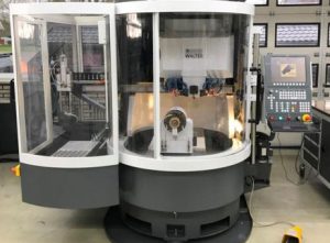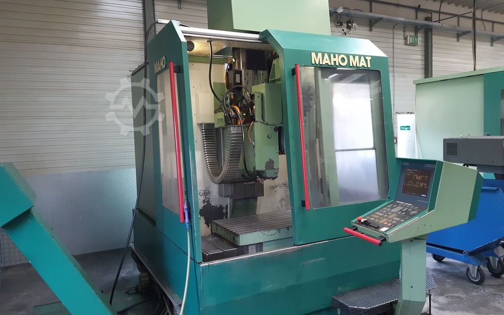
Technical Buyer’s Handbook: Assessing Pre-Owned , Used , Secondhand, Surplus CNC Machines Before Purchase MAHO MAT 500 CNC Milling Machine made in Germany
Below is a Technical Buyer’s / Due-Diligence Handbook / Inspection Checklist for evaluating a pre-owned / used / surplus MAHO / MAT-500 (or “MAHO MAT 500”) CNC milling machine (bed- or column type, made in Germany). (“MAT” is a MAHO series prefix; many listings refer to “MH 500” variants, so adjust accordingly.) Use this as a detailed guide and adapt tolerances, priorities, and weightings to your shop’s needs (accuracy, size, spindle power, etc.).
I have also included reference data from publicly listed MH / MAHO 500 machines to act as benchmark targets you can compare against.
0. Reference / Benchmark Specifications (for MAHO / MH / MAT 500 Series)
Before you go inspect, gather the exact spec sheet for the particular serial / configuration. Meanwhile, here are typical specs from used MH-500 machines which are in the same family and useful as benchmarks:
| Parameter | Typical / Published Value |
|---|---|
| Travel (X × Y × Z) | 500 mm × 380 mm × 350 mm |
| Table dimensions | 800 mm × 355 mm |
| Spindle speed | Up to ~4,000 rpm, lower speeds around 63 rpm available |
| Tool holder / taper | ISO 40 (common in these machines) |
| Machine weight / footprint | Example: 3,200 kg, footprint ~ 2,100 × 1,800 × 1,900 mm (length × width × height) for MH 500 W variant |
| Power / drives / feeds | Rapid / feed speeds ~5,000 mm/min (for some units) |
| Control system seen | “Philips 432 / CNC 432” in some listings |
These benchmarks are not exact for every MAT-500 but are good targets. When inspecting a candidate machine, deviations from these should be explained or compensated in your offer or refurbishment plan.
I. Pre-Inspection / Remote Preparation
Before traveling, do as much preparatory work as possible:
- Request full documentation
- Manufacturer manuals: mechanical, electrical, pneumatic / lubrication
- Wiring diagrams, control schematics, I/O maps
- CNC parameter backups, axis tuning / compensation files
- Maintenance / service logs (repaired axes, spindle rebuilds, linear guide replacements)
- Calibration / alignment / inspection certificates
- Modification / retrofit history (e.g. added probing, spindle upgrades)
- Spare parts / BOM list - Request photos & videos
Ask for clear, high-resolution images or video of:
• The machine’s exterior (frame, column, base)
• Table, guideways, linear axes, ball screws
• Spindle head and nose, tool mount, spindle motor
• Control cabinet interior (drives, wiring, connectors)
• Motion demo (axis jogging, spindle rotation, tool change) if still powered
• Underside, bed surfaces, coolant troughs - Ask key questions
- Year, serial number
- Total operating hours, duty cycle (heavy use vs light use)
- Reason for sale or decommission
- Any known faults, collisions, major repairs
- What parts / tooling / fixtures are included
- Is it currently functional / powered or has been disconnected
- Control system version, software, backup state - Plan inspection tools & instruments
Bring or plan to have:
- Dial indicators, micrometers, test bars, straight edges
- Laser alignment tools (if available)
- Vibration / accelerometer sensor / portable vibration analyzer
- Thermography / infrared camera
- Feeler gauges, calibration blocks
- Tools to open panels, inspect wiring - Logistics / site evaluation
- Weights, rigging / crane access, lifting points
- Foundation / floor load capacity, flatness
- Power supply (voltage, phase, availability)
- Coolant, lubrication, air, exhaust systems
- Space clearance around machine for service & motion
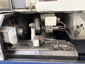
II. Visual & Structural Inspection (Cold / Power-Off)
Before powering anything, do a careful survey of all structural and mechanical components.
2.1 Frame, Base & Structure
- Inspect the machine’s base, column, and frame castings for cracks, weld repairs, distortions or signs of stress
- Examine leveling pads, base plate shim areas, anchor points for warpage or deterioration
- Check for corrosion, pitting, especially in coolant zones, chip areas
- Inspect covers, guards, way covers, bellows, seals for damage, missing parts, wear
- Check that machine appears level, not twisted (use straight edges)
2.2 Linear Axes, Guideways, Carriages, Ball Screws
- Inspect guide rails, sliding surfaces, ways for scuffs, scoring, wear marks, pitting
- Examine ball screws / lead screws for backlash, wear, damage
- Manually (if allowed) slide axes to check smoothness, binding, grit
- Check carriage play, side play or looseness
- Inspect lubrication lines, fittings, check for clogging or leaks
2.3 Spindle / Head / Tool Interface
- Examine the spindle nose, taper, threads, clamping surfaces for wear, damage, signs of misalignment
- Inspect spindle motor coupling / connection
- Check seals, cooling / lubrication supply to spindle, check for leaks
- If possible, mount a test bar (non-driven) and check static run-out
- Inspect the spindle housing for discoloration / overheating signs
2.4 Tool Change / Magazine (if applicable)
- Inspect tool changer arms, grippers, slides for backlash, wear
- Check sensors / proximity switches for alignment / damage
- Inspect magazine pockets, indexing mechanisms
- Check cables, wiring to tool changer mechanisms
2.5 Electrical / Control Cabinet & Wiring Infrastructure
- Open cabinets (if permitted) and inspect wiring terminals, connectors, insulation condition
- Look for discoloration, burned insulation, loose conductors
- Inspect drive modules, power modules, control boards for signs of overheating or damage
- Check cooling fans, filters, ventilation paths, dust buildup
- Inspect cable routing, strain relief, motion cable carriers for damage
2.6 Safety, Guards & Interlocks
- Verify existence and mechanical integrity of Emergency Stop (E-stop) buttons
- Inspect guards, door interlocks, safety covers
- Check limit / home switch presence and physical condition
- Confirm no safety systems appear bypassed or overridden
III. Power-Up & Functional / Dynamic Testing
Once static inspection is acceptable and safety is assured, with caution power up and run dynamic tests.
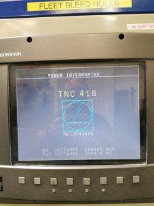
3.1 Initial System Power-On & Diagnostic Checks
- Power up the control & CNC system; observe boot sequence, errors, warnings
- Confirm CNC parameters load correctly, no memory corruption
- Check I/O status: limit, home, safety inputs, sensor signals
- Jog axes at low speed: check direction correctness, smooth motion, no binding
3.2 Homing / Reference / Zeroing Cycles
- Execute homing or referencing for axes (X, Y, Z)
- Repeat multiple times to check consistency (back-to-back homing)
- Trigger limit switches intentionally to verify safe limit behaviors
3.3 Axis Travel & Accuracy Trials
- Move each axis through full safe travel at moderate speed, listening for jerk, stiction, binding
- Command known distances (e.g. 100 mm) and measure actual movement (via dial gauge / test device)
- Reverse direction, measure backlash or dead-band
- If available, run straight-line or circle motions to check cross-axis coupling or distortion
3.4 Spindle Running Behavior
- Run spindle at low rpm and gradually ramp up; monitor for vibration, noise, abnormal behavior
- If safe, mount a test workpiece or test bar, measure run-out under rotation
- Monitor spindle motor current, temperature behavior
- Check lubrication / cooling to spindle under running
3.5 Tool Change / Tool Handling Tests
- Execute multiple tool change cycles; observe motion smoothness, sensor feedback, accuracy
- Cycle tool changes repeatedly to test reliability
- Try changing tools of varying sizes (within safe limits)
3.6 Test Cut / Machining Simulation (if permitted)
- Run a light-cut test on soft material (e.g. aluminum) to simulate real usage
- Compare resulting part dimensions vs programmed path, inspect surface finish
- Let the machine run for a period to allow thermal effects, drift
- Monitor vibration, current draw, deviations over time
3.7 Safety / Fault Response Tests
- Activate E-stop during active motion or spindle run, verify safe shutdown
- Trigger limit switches or signal faults to check controlled stoppage
- Simulate sensor failures if safe, view error recovery behavior
- Open guards during motion to test interlocks function
3.8 Stability / Endurance / Drift Tests
- Run motion cycles or idle for 30–60 minutes to let thermal stabilization
- After warm-up, re-check key axes, backlash, repeatability
- Monitor motor / drive / controller temperatures
- Use thermography / vibration analysis to detect developing problems
IV. Precision, Calibration & Accuracy Checking
Once the machine is stable (thermally and mechanically), test precision and calibration.
- Repeatability test: move to the same coordinate, retract, return, measure deviation
- Grid motion test: command a lattice of X–Y or X–Y–Z moves, measure deviations across workspace
- Squareness / orthogonality tests: e.g. move in X then Y vs Y then X, check differences
- Spindle overlay / alignment tests: if possible, test alignment between spindle axis and linear axes
- Under load / offset conditions (e.g. offset setup), observe deflection or deviation
- If you have high-precision tools (laser interferometer, calibration bars), use them for fine error mapping
- Compare measured errors vs acceptable tolerances (based on your application or machine’s original spec)
V. Documentation & History Review
When you’re satisfied with mechanical / dynamic tests, review all historic and supporting documentation:
- Maintenance / repair logs (major work: guide replacement, spindle rebuilds, axis overhauls)
- Calibration / alignment certificates
- Retrofitting / modifications (CNC upgrades, spindle changes, added probing)
- CNC / control software version history, backup files
- Spare parts inventory included (lin. rails, ball screws, spindle parts, electronics)
- Tooling / fixtures / accessories provided
VI. Risk Assessment, Life-Remaining Estimate & Cost Forecasting
From your inspection results, build a risk / cost model.
- Identify high-wear subsystems: spindle bearings, guide rails, ball screws, tool changer mechanisms
- Assess availability of spare parts (MAHO / German machine tool spares) and lead times
- Estimate cost for calibration / realignment / compensation tuning after relocation
- Consider transport / reinstallation risk (damage, alignment shifts)
- Estimate commissioning / downtime cost
- Consider control / electronics obsolescence risk
- Consider salvage / fallback value (structure, non-wear parts)
You may build a weighted scoring table (structure, axes, spindle, tool changing, control) to quantify condition and calibrate your maximum acceptable price or repair allowance.
VII. Contractual Safeguards & Negotiation Clauses
Based on your findings, include protections in your purchase agreement:
- Acceptance / test clause: allow buyer to test machine after installation; condition sale on meeting agreed performance metrics
- Price adjustment clause: if measured performance deviates beyond agreed tolerances, seller agrees to reimburse remedy cost
- Warranty / latent defect clause: limited coverage period (e.g. 3–6 months) on hidden faults
- Spare parts package: require inclusion of critical wear parts (rails, screws, bearings, seals, electronics)
- Documentation handover clause: all manuals, wiring, backup parameter files, alignment / calibration records
- Transport / insurance clause: clearly allocate risk / liability during shipment
- Installation / commissioning support clause: seller or technical support assist during first commissioning and calibration
VIII. Post-Purchase / Installation & Commissioning Checklist
Once the machine is relocated and installed, proceed methodically:
- Prepare foundation, leveling, anchoring, vibration isolation
- Clean and flush lubrication / coolant / hydraulic circuits; replace filters / fluids as needed
- Re-mount and check guards, covers, safety interlocks
- Power up and repeat your full acceptance / dynamic / precision tests
- Perform alignment, geometry calibration, error compensation
- Run test parts in actual materials to validate performance under your workload
- Capture baseline data (repeatability, drift, backlash)
- Train operators & maintenance staff
- Establish preventive maintenance / inspection schedule
- Monitor performance (drift, alarms, deviations) especially during the early weeks of production