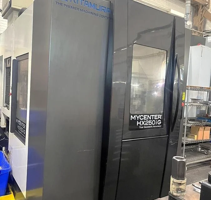
Technical Buyer’s Handbook: Assessing Pre-Owned , Used , Secondhand, Surplus CNC Machines Before Purchase Kitamura HX-250iG CNC Horizontal Machining Center with 4th Axis Rotary Table made in Japan
Here is a Technical Buyer’s / Due-Diligence Handbook / Checklist tailored for evaluating a pre-owned / used / surplus Kitamura HX-250iG (HX250iG) horizontal machining center, especially when it includes a 4th-axis rotary table or pallet indexing. Use this as a master reference and adapt it to your tolerances, tooling, and risk tolerance.
0. Reference & Baseline Specifications (Kitamura HX-250iG)
Before inspection, have on hand the nominal specs so you can judge deviations. Below are typical published numbers for the HX250iG:
| Parameter | Spec / Nominal Value |
|---|---|
| Table size | 254 × 254 mm (10″ × 10″) |
| Travels (X, Y, Z) | 305 × 305 × 330 mm (12″ × 12″ × 13″) |
| 4th-Axis (B / rotary) | Full 0–360° indexing, B-axis rapid 108,000 °/min (300 min⁻¹) |
| Spindle taper | NST No. 30 standard (option HSK-E40) |
| Spindle speed | 150 – 15,000 RPM standard (option up to 30,000 RPM) |
| Spindle motor & torque | 11 kW (15 HP) for 30-min duty, 7.5 kW continuous, max spindle torque ~70 N·m (for the 15k version) |
| Rapid / feed rates | Rapid feed X/Y/Z: 60 m/min (≈2,362 ipm) |
| Positioning / repeatability | ±0.002 mm full stroke, ±0.001 mm repeatability (typical) |
| Utilities & footprint | Power: ~30 kVA, 200 V 3-phase Footprint: ~2,330 × 2,948 mm (W × D) Height: ~2,470 mm, Machine net weight ≈4,500 kg |
These specs form your benchmark. If the candidate machine deviates significantly (e.g. slower spindle, worn axes, incorrect indexing behavior), you will need justification or remedial work.
1. Pre-Inspection / Remote Phase
Before you visit the site, gather as much information as possible to reduce surprises.
- Request full machine & rotary table documentation
- Mechanical, electrical, hydraulic / pneumatic manuals
- Wiring diagrams, control parameter backups, motion tuning files
- Rotary (4th-axis) table / indexing drive documentation, control interface specs
- Maintenance / service logs, repair history
- List of replaced major components (ball screws, guideways, spindle rebuilds, rotary drive)
- Calibration and alignment certificates or records
- Modification / retrofit history (e.g. changes in spindle, sensors, table, control upgrades) - Ask key questions / data points
- Year of manufacture, cumulative hours / cycle count
- Duration and nature of use (light, heavy, precision work, roughing)
- Reason for sale / decommission
- Whether the machine is currently operational
- Known problems or defects (vibration, accuracy drift, axis issues)
- Whether tooling, fixturing, rotary table are included
- Control / CNC version, feature licenses, software updates - Request photos & videos
- Exterior: all sides, base, column
- Control cabinet interior, wiring, drives, boards
- Spindle nose, taper, tool holder region
- Guideways, ways, ball screws
- Rotary table: top surface, indexing drive parts, connection to machine
- Motion videos: axis jog, rotary indexing, tool changes
- Any parts that are suspect (wear, corrosion, damage) - Plan tools and measurement set-up
Bring dial indicators, micrometers, straight edges, test bars, borescope, vibration meter, thermography, laser alignment system (if available). - Logistics planning
Check floor space, crane / rigging capacity, power supply, access paths, foundation, machine weight.
2. On-Site Visual & Structural Inspection (Power-Off / Cold Inspection)
Once on-site, before powering up (or in parallel), do a thorough physical and structural check.
2.1 Machine Structure & Enclosure
- Check the castings, base, column, frame for cracks, repairs, deformation, evidence of welding or rework.
- Inspect leveling shims, base supports, anchoring points.
- Look over protective covers, doors, guards, seals, hinges.
- Inspect way covers, bellows, wipers, lubrication covers — look for damage, missing parts, misalignment.
- Inspect chip conveyor, coolant tank, piping, coolant filtration units for leaks, corrosion, debris.
2.2 Linear Axes (X, Y, Z) & Motion Components
- Manually (if possible) move axes a small amount to feel for roughness, binding, stick-slip.
- Use straight edges / feeler gauges to check flatness, parallelism of ways.
- Inspect ball screws, leadscrews, nuts for wear, pitting, backlash.
- Check anti-backlash mechanisms, preload adjustment mechanisms.
- Inspect linear guide rails for wear marks, chips, scoring.
- Inspect lubrication lines / systems — make sure they’re intact, not clogged, leak-free.
2.3 Spindle & Tooling Interface
- Inspect spindle nose, taper, threads, clamping surfaces for wear, nicks, damage.
- Remove tool holders (if possible) and inspect seat surfaces.
- Check spindle interior (if accessible) for signs of overheating, discoloration.
- Use a test bar (if allowed) to check static run-out at room temperature.
- Inspect cooling and lubrication circuits to spindle, including seals.
2.4 Rotary Table / 4th Axis (B-axis) Components
- Inspect the rotary table face, fixture surfaces, mounting interfaces.
- Check spindle / indexing drive unit for wear, oil leaks, gearboxes, couplings.
- Attempt gentle manual rotation (if permitted) to sense smoothness, binding, incremental indexing.
- Inspect rotary bearing seals, lubrication access, rotation encoders or feedback devices.
- Inspect wiring, connector cables for the rotary drive (especially in moving cables).
2.5 Tool Magazine / Tool Changer (if present)
- Inspect tool changer arms, grippers, slides, indexing mechanism.
- Check for wear, looseness, gear play in tool changer actuation.
- Inspect sensor switches, alignment sensors, pneumatic / hydraulic actuators.
- Manually test (if possible) partial tool changer motion to sense binding or misalignment.
2.6 Electrical Cabinets, Wiring & Control Hardware
- Open CNC / motion control cabinets (if permitted) and inspect internal condition: dust, corrosion, burned insulation, scorch marks.
- Inspect servo drives, amplifiers, DC bus capacitors (bulging, leakage), power supplies.
- Check terminal blocks, wiring routing, connectors, cable strain reliefs.
- Inspect fans, filters, ventilation paths, cooling of enclosures.
- Examine cables in drag-chains / carriers (particularly to rotary axis) for abrasion or fatigue.
- Check grounding, shielding, bonding on all panels.
2.7 Safety & Guards
- Verify E-stop buttons, their wiring and mechanical function.
- Inspect door interlocks, safety limit switches, guard slides.
- Confirm no safety circuits are bypassed.
- Validate presence and integrity of guarding on moving parts, covers that move or retract.
3. Power-Up, Functional & Dynamic Testing
With caution and in cooperation with the seller or maintenance staff, power up and perform a series of tests. Safety is critical.
3.1 Initial Power-Up & Diagnostic Checks
- Power the machine, observe boot sequence, error / alarm logs.
- Check CNC parameter memory, verify no corruption or missing settings.
- Verify I/O status, limit switches, homing circuits.
- Jog axes slowly (X, Y, Z, and B) and monitor for smooth movement, correct direction, no stiction or abnormal noise.
3.2 Homing / Referencing Cycles
- Run homing / referencing on all axes (X, Y, Z, B).
- Repeat multiple times to check home repeatability (i.e. difference each time).
- Check soft and hard limits for each axis; verify axes do not overshoot or crash.
3.3 Axis Travel, Linear Motion & Backlash Tests
- Move each axis across its full safe travel path at moderate speed, observe for jerks, binding, abnormal vibration or noise.
- Command known distances (e.g. 100 mm, 50 mm) and measure with a dial gauge or standard reference to check linear accuracy.
- Reverse direction and measure backlash or dead-band.
- If possible, use a ball-bar or laser interferometer (if available) to test linearity, straightness, and geometric errors.
3.4 Rotary (4th Axis) Motion / Indexing Tests
- Command B-axis (rotary) motions through multiple angles (e.g. 10°, 30°, full 360°) and verify correctness and smooth motion.
- Test the indexing behavior: e.g. move a precise angular increment and check if the actual angle matches.
- Rotate repeatedly to observe drift, slippage, or backlash in the rotary mechanism.
- Test the clamping / locking of the rotary axis in dwell mode (is it stable, no drift?).
3.5 Spindle Run Test
- Start spindle at a low RPM, monitor sound, vibration, temperature rise.
- Gradually ramp up speed to full rating (if safe) and check for unusual noises or vibrations.
- Use a dial indicator on a test bar to measure spindle run-out under rotation.
- Monitor motor current, torque, coupling stability.
- Verify cooling / lubrication feeding to spindle under operation.
3.6 Tool Change & Magazine Function
- Command tool change sequences to test arms, sensors, grippers.
- Cycle several tools repeatedly to observe reliability, jamming, sensor errors.
- Check tool change timing, consistency, placement accuracy.
- Ensure sensors or interlocks function properly (no false positives or misses).
3.7 Simulation / Test Cut (if permitted)
- If safe and allowed, perform a light test cut on an inexpensive workpiece (e.g. aluminum or soft material) to replicate real operating conditions.
- Monitor forces, power draw, chatter, dimensional accuracy of the cut piece vs commanded model.
- Inspect surface finish, geometry errors, drift over time.
- Let the machine run for a sufficient period (30–60 min) to detect any thermal drift or loosening.
3.8 Safety / Fault Behavior Tests
- Test E-stop during different active modes (idle, axis motion, spindle) to ensure immediate, safe stopping.
- Trigger limit switches (soft and hard) to confirm axes stop or back off as expected.
- Simulate fault conditions (sensor fail, unexpected interruption) to check how the system recovers or errors.
- Test interlocks: e.g. blocking rotary motion while spindle is active, safety gating during tool change.
3.9 Extended Run / Stability / Thermal Drift
- Run a “warm-up / stabilization” routine: moderate motion, spindle idle, no load for 30+ minutes.
- After stabilization, re-check positioning accuracy, backlash, repeatability to detect drift.
- Monitor temperature of drives, spindle, control cabinet, motors.
- Use a vibration meter / accelerometer to detect resonance or abnormal vibration emerging over time.
4. Precision, Accuracy & Calibration Validation
Once the machine is warmed and stable, test how accurately it performs compared to expected tolerances.
- Execute a repeatability test: move to a point, retract, return, measure deviation.
- Run a grid of points motion (e.g. a calibration pattern) and measure deviations; map linearity error, scale error, angular tilt.
- For the rotary axis, command angular moves and measure angular deviation (e.g. using high-precision rotary encoder or angular gauge).
- Carry out 4-axis simultaneous programming tests (linear + rotary) and measure resulting geometric deviation.
- Measure scale / thermal expansion / drift by doing repeated measurements at multiple times.
- Check surface finish on test cuts, th referential geometries (e.g. perpendicularity, parallelism) on a known part.
- If you have access to more advanced calibration tools (laser interferometer, ball-bar, probing systems), incorporate them.
- Compare actual machine performance to manufacturer spec (±0.002 mm or so) and your required tolerances.
5. Documentation & Service History Review
After the physical and dynamic tests, review all the background and support documentation.
- Maintenance / service logs: preventive maintenance, breakdowns, repairs.
- Major rebuilds or replacements (ball screws, bearings, spindle overhauls).
- Calibration / alignment certificates or reports.
- Retrofit or modification records (control upgrades, sensor changes, added instrumentation).
- CNC / control software version history, parameter backups, interface / communication module history.
- Spare parts inventory (if included) and list of critical wear parts already replaced.
- Tooling, fixturing, rotary table accessories included.
6. Risk Assessment, Life-Remaining Forecast & Cost Estimation
Based on the inspection data, you’ll want to estimate residual life and risk exposures:
- Wear-critical elements: ball screws, guide rails, anti-backlash nuts, spindle bearings, rotary bearings, tool changer mechanisms — assess how worn they appear and estimate remaining life.
- Spare parts / support: check availability of genuine parts (Kitamura or aftermarket), lead times for motors, sensors, control parts, encoders.
- Calibration / alignment cost: after relocation and installation, you’ll need full calibration and possibly adjustment; budget for that.
- Transport / reinstallation risk: disassembly, shipping damage, leveling, repositioning, foundation work.
- Downtime / commissioning time: time to get the machine operational in your facility.
- Control / obsolescence risk: how old is the CNC / control hardware, whether parts or software modules are becoming obsolete.
- Fallback / salvage value: in worst-case, what parts or structure could be salvaged.
You may build a weighted risk matrix, scoring each subsystem (axes, spindle, rotary, control, etc.) and aggregate into an adjusted offer price.
7. Contractual Safeguards & Negotiation Levers
Use your inspection findings to negotiate protective terms:
- Acceptance / Test Pass Clause: purchase contingent on passing your post-installation performance tests.
- Spare Parts Package: require the seller to include a kit of critical wear parts (e.g. bearings, seals, tool changer parts).
- Documentation Warranty: seller must deliver all manuals, schematics, parameter backups, software, and rotary table docs.
- Warranty / Hidden-Defect Guarantee: limited period (e.g. 3–6 months) coverage against undisclosed defects.
- Price Adjustment Clause: if after inspection or commissioning some parameters are off by X %, you deduct estimated repair cost.
- Shipment / Insurance Clause: define who bears risk during transport, damage control.
- Installation / Commissioning Support: seller (or their representative) to support first setup / alignment at your site.
8. Post-Purchase / Installation & Commissioning Checklist
After delivery and installation, perform the following:
- Foundation, leveling, anchoring, vibration isolation.
- Clean the machine thoroughly; flush coolant / lubrication systems; replace fluids, filters.
- Verify covers, guards, seals, safety systems.
- Power up and rerun your acceptance tests (axis accuracy, speed, rotary indexing, tool change, spindle).
- Perform full calibration, alignment, error compensation (geometric, thermal).
- Run trial production parts and verify performance in your workload conditions.
- Document as-installed baseline (backlash, drift, axis errors) for future reference.
- Train operators & maintenance staff on idiosyncrasies.
- Schedule preventive maintenance / inspection plan.
- Monitor performance metrics (error drift, alarms, vibration) during early weeks and compare to baseline.