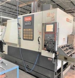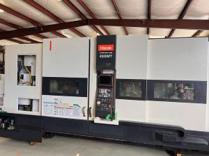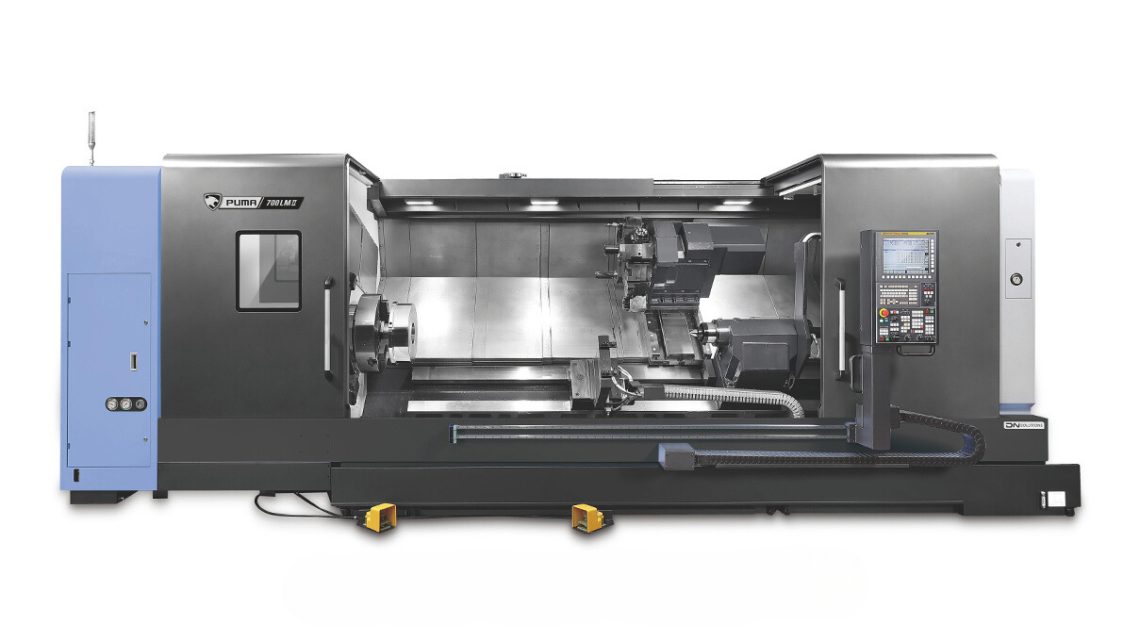
Technical Buyer’s Handbook: Assessing Pre-Owned , Used , Secondhand, Surplus CNC Machines Before Purchase DN SOLUTIONS Puma 800B II CNC Heavy Duty HTC Turning Center made in South of Korea
Here’s a Technical Buyer’s / Due-Diligence Handbook / Checklist you can use (and adapt) when evaluating a pre-owned / used / surplus DN Solutions (Doosan) PUMA 800B II heavy-duty CNC turning center. This is intended to help you systematically assess condition, risk, and value before committing.
I’ll begin by summarizing key specs of the PUMA 800B II (so you know what “ideal condition” should be close to), then present a structured inspection, testing & evaluation checklist, risk assessment, negotiation tips, and post-purchase considerations.
You can convert this into a printable / on-site checklist (Excel / PDF) for your own inspections.
0. Key Reference Specifications (PUMA 800B II)
Before inspecting, you should know what the nominal spec ranges are, so you can spot deviations. From manufacturer / catalog sources:
| Parameter | Spec / Nominal Value |
|---|---|
| Max turning diameter | Ø 900 mm (35.4 in) |
| Max turning length / workpiece length (standard) | 1,600 mm (63 in) |
| Spindle max speed | 500 RPM |
| Spindle power / torque | ~ 55 kW (≈ 74 hp) and 8,076 N·m torque |
| Spindle through-hole diameter | Ø 375 mm (14.8 in) |
| Rapid traverses | X-axis 12 m/min, Z-axis 16 m/min |
| Tool turret / stations | 12 tool stations (BMT style) |
| Tailstock quill / travel | Quill 160 mm dia, travel ~150 mm |
| Machine dimensions / weight | Length ~5,756 mm, height ~2,800 mm, width ~3,160 mm, weight ~16,500 kg |
These are your baseline “reference” numbers. A used machine should be close to these, or deviations must be explained and acceptable within your use-case.
1. Pre-Inspection & Preparation (Desk / Remote Phase)
Before traveling to the site, do the following:
- Request documentation from seller
- Original factory manuals (electrical, control, mechanical)
- Wiring diagrams, PLC / CNC program backups, servo parameter backups
- Maintenance / servicing history, service logs
- Parts replacement logs (which major parts have been replaced, when)
- Calibration / alignment certificates (if done)
- Any modification records or retrofits (e.g. added axes, custom fixtures) - Request photos / videos
- Exterior (front, side, rear)
- Control cabinet, panel interior, wiring harnesses
- Spindle interior, chuck, turret, tool holders
- Slideways, guideways, way covers
- Tailstock, quill, tooling, chuck jaws
- Motion videos (if machine running): tool change, spindle run, axis jogging - Ask key preliminary questions
- Age / years in service
- Workhours or duty cycle (if known)
- Reason for selling
- Whether machine is currently operable
- Any known defects / issues
- Whether spare parts or tooling come with machine - Plan logistics & measurement tools
Bring precision gauges, dial indicators, micrometers, laser alignment tools, vibration meter, thermography camera (if available), multimeter, inspection mirror, borescope, etc.
Also plan for power requirements, crane / lifting, floor plan.
2. Visual & Structural Inspection (Before Power-Up)
Do this before or during power-off condition to catch obvious structural or mechanical defects.
2.1 External / Structural Integrity
- Check machine body, base, bed, casting for cracks, repairs, distortion, welds, misalignments.
- Look for signs of corrosion, rust (especially in coolant zones or base).
- Inspect covers, guards, doors, hinges, seals, windows.
- Check way covers, bellows, wipers for damage, tears, deformation.
- Examine chip disposal paths, chip conveyors, coolant return paths for blockage or damage.
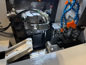
2.2 Spindle / Chuck & Tooling
- Inspect spindle nose, taper, keying surfaces, threads for wear or damage.
- Check chuck jaws: condition, alignment, signs of wear, repair.
- Remove jaws (if possible) to inspect jaw seat surfaces.
- Inspect turret, tool holders, turret seating surfaces, clamps.
- Check for run-out or wobble in spindle with a test bar (if possible, before powering).
- Inspect tooling, holders, boring bars for condition.
2.3 Slideways, Guideways, Ball Screws / Leadscrews
- Slide the axes manually (if possible) and feel for binding, roughness, scoring, sticking points.
- Use a straight edge / indicator to check for flatness and alignment of the ways.
- Inspect ball screws / leadscrews for wear, pitting, grease state, backlash.
- Check for looseness or play in axes (X, Z).
- Check for wear on anti-backlash devices (nuts, preloads).
- Inspect linear guide rails (if any) for wear, chips, scarring.
2.4 Turret, Tool Magazine & Tool Change Mechanisms
- Inspect turret mechanism for smooth rotation, backlash, wear in gear teeth.
- Check tool magazine / carousel (if applicable) for indexing accuracy, wear.
- Inspect pneumatic / hydraulic actuators, clamps, sensors for wear or leaks.
- Inspect cam followers, guide surfaces, indexing pins.
2.5 Tailstock & Quill
- Inspect tailstock alignment, quill movement, seals, locking mechanism.
- Check quill for play or wobble.
- Verify tailstock alignment with bed axis (X / Z).
2.6 Cooling / Lubrication / Pneumatic / Hydraulic Systems
- Inspect lubrication lines, pumps, filters, reservoirs; check for leaks, blockages, degraded hoses.
- Check coolant tanks, pumps, piping, nozzles, filters for contamination, wear, leaks.
- Check coolant return paths, sumps, overflow, drain lines.
- Inspect hydraulic systems (if any) for leaks or pressure holding.
- Check pneumatic lines, valves, couplings for leaks, cleanliness.
- Filter elements, screens, reservoir cleanliness.
2.7 Electrical Enclosures, Wiring & Cabinet
- Open control / drive cabinets (if permitted) and inspect for dust, corrosion, burned wires, signs of overheating, insect or rodent damage.
- Look for discoloration, melted insulation, loose terminal blocks.
- Inspect servo drives, power drives, I/O modules, CPU, wiring routing.
- Check fans, filters, ventilation paths.
- Inspect cable drag-chains, carrier rails, cable harnesses, connectors along moving axes.
- Check grounding, bonding straps.
2.8 Safety, Guards & Interlocks
- Verify emergency stop buttons and their wiring / function (mechanical continuity).
- Inspect safety interlock switches, door interlocks, guard sensors.
- Check that guards are present and not bypassed.
- Check covers for wiring paths, shielding.
3. Power-Up, Functional & Performance Testing
If seller allows, power up the machine and run functional / dynamic tests under controlled conditions. Use caution — support a “cold start” process and supervise safety.
3.1 Initial Power-Up & Control Diagnostics
- Power up CNC / control, observe boot sequence, error messages, alarms.
- Check parameter / configuration memory integrity (no errors).
- Run auto-diagnostics, status screens, error logs.
- Verify I/O status, limit switches, homing systems.
- Jog axes at low speed to check smoothness and direction correctness.
3.2 Homing / Referencing
- Execute homing cycle; each axis should home reliably without hitting hard limits.
- Repeat several times and check consistency of home position (repeatability).
3.3 Axis Movement / Travel Testing
- Move axes full travel in X and Z at moderate speeds; watch for stiction, jerks, unusual noise.
- Measure backlash / slack by reversing direction and observing dead zone.
- Use a dial indicator or test gauge to check straightness, linearity in movement.
- Command known distances (e.g. 100 mm) and measure actual travel with gauge to assess linear accuracy.
3.4 Spindle / Rotation Testing
- Run spindle at low rpm, gradually increase to full rpm (or near spec) and observe vibration, noise, smoothness.
- Use a dial test indicator on a test bar to check spindle run-out.
- Monitor temperature rise, stability under no load.
- Check spindle bearings: listen / feel for roughness.
3.5 Tool Change / Turret Operation
- Execute tool change cycles; monitor time, smoothness, accuracy of indexing.
- Insert tools into various turret station positions, run motion, verify no collision, smooth operation.
- Check turret repeatability by commanding tool offsets, verifying against measurement.
- Cycle tool changes repeatedly to test robustness.
3.6 Load / Cutting Simulation (If safe)
- If possible—under light / controlled load—attempt simple cutting of a test workpiece or dummy load.
- Monitor CNC for load current, torque, stability.
- Check part tolerances, surface finish, dimensional accuracy vs tool path.
- Observe thermal drift over a short run (e.g. 30 minutes).
3.7 Safety / Behavior Under Fault
- Trigger emergency stop (E-stop) and verify machine halts immediately and safely.
- Test limit switch operation (move to soft or hard limits) and check behavior.
- Introduce recovery sequences, abrupt stops, reversals and observe system recovery, errors.
3.8 Thermal / Stability / Drift Test
- Run machine for extended period (if permitted) to let temperatures stabilize (30–60 min).
- Re-check positioning accuracy, backlash, thermal drift, expansion effects.
- Monitor temperature of drives, servo motors, spindle.
3.9 Noise, Vibration, and Condition Monitoring
- Use vibration meter (if available) at various positions (spindle housing, turret, axes) to detect high-level vibration harmonics.
- Listen/feel for scraping, knocking, bearing noise, resonance.
- Infrared thermography (if available) to detect hot spots in drives, wiring, bearings.
4. Precision / Calibration / Accuracy Validation
This is where you check how closely the machine performs relative to its nominal specs (or to your required tolerances).
- Use gauge blocks, micrometers, test bars to measure actual work displacement.
- Feed a calibration test piece (e.g. straight bar) and measure against commanded dimensions (diameter, length) to gauge cumulative error.
- Perform repeated positioning tests (e.g. move to a point, retract, return) and measure difference (repeatability).
- Check angular alignment of spindle axis vs bed axis.
- Use laser alignment / ball bar testers if available.
- Check taper geometry of spindle bore (if measuring internal work).
- Measure chatter, surface finish under light tools.
- If you have access to a known reference part, compare actual vs programmed.
5. Documentation, History & Service Records Review
After physical assessment, review the machine’s background:
- Maintenance logs: service dates, replaced parts, breakdowns, unscheduled repairs.
- Records of major overhauls (spindles, gearboxes, turrets).
- Calibration / alignment certificates over time.
- Modification history: have there been non-standard upgrades or “field fixes”?
- Software / firmware upgrade history, backups.
- Original parts list, spare parts inventory, tooling assets.
- Operator / usage history: how many shifts, duty cycle, workload profiles.
6. Risk / Condition Scoring & Cost Projection
You should estimate residual life of critical components and risk premiums. Here’s how:
- Wear elements / replaceables: spindle bearings, turret indexing mechanisms, ball screws, guideways — estimate remaining life.
- Spare parts availability: For Doosan / DN Solutions in your region, check lead times and cost for spares (e.g. bearings, drives, motors, CNC modules).
- Calibration / realignment cost: after transport and reinstallation, you’ll need alignment, calibration — budget for that.
- Transport / rigging risk: disassembly/ reassembly, shipping damage, leveling, foundation adjustments.
- Downtime & commissioning cost: time to get machine production-ready.
- Obsolescence & compatibility: control electronics age, spare parts obsolescence, interface compatibility with your CNC ecosystem.
- Salvage / fallback value: in worst case, what is recoverable value of castings, components, structures.
You can build a weighted scoring matrix. For example:
| Factor | Weight | Score (0–10) | Comments |
|---|---|---|---|
| Spindle condition | 20% | ||
| Turret / tool changer | 15% | ||
| Axes / ball screw / guideways | 15% | ||
| Electrical / control / drives | 15% | ||
| Service / documentation / history | 10% | ||
| Accessibility of spares | 10% | ||
| Transport / reinstallation cost | 5% | ||
| Performance under test | 10% |
Set a threshold or adjust price accordingly.
7. Negotiation & Contract Safeguards
Use your inspection to negotiate better terms and safeguards:
- “Acceptance Test” Clause: the machine must pass your tests (e.g. within tolerance, full motion) after arrival/installation or you reserve rights to reject / adjust price.
- Spare Parts Package: the seller provides a kit of key wear/spare parts (e.g. bearings, seals, tools).
- Documentation Delivery Guarantee: all manuals, backups, wiring diagrams, software, parameter files must be handed over.
- Warranty / Return Period: short-term warranty (e.g. 3–6 months) on hidden defects.
- Adjustment for Deviations: if certain parameters are off (e.g. excessive backlash, spindle wear), deduct cost for corrections.
- Shipping & Insurance Clause: define who bears risk during transport.
- Installation / Commissioning Support: seller or third party helps with first turn / alignment at your site.
8. Post-Purchase / Installation & Commissioning Checklist
After acquisition, do the following before putting the machine into full production:
- Machine siting, foundation, leveling, vibration isolation.
- Full cleaning, flushing of coolant / lubricant systems, replacement of fluids / filters.
- Reassemble and verify all covers, guards, seals.
- Power up and run your acceptance tests (again).
- Perform full calibration / alignment under your site conditions.
- Run test parts for your real workload and verify tolerances.
- Document “as-installed baseline” readings (backlash, positioning errors, thermal drift) for future reference.
- Train your operators / maintenance staff on the machine’s idiosyncrasies.
- Set up maintenance / preventive service schedule.
- Monitor first weeks closely for any drift or anomalies.