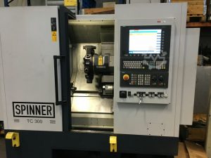

Smart Buyer’s Guide: How to Choose the Right Pre-Owned, Used, Secondhand, Surplus CNC Equipment Before Purchasing Spinner TC300 SMCY CNC Turning Center made in Germany
If you’re evaluating a Spinner TC300 SMCY (or similar universal / turn-milling Spinner TC line) as a used / surplus CNC machine, here is a Smart Buyer’s Guide: a structured checklist, red flags, negotiation tactics, and Spinner-specific considerations to help you make an informed decision.
Below is how I’d approach it step by step:
Key Baseline Specs & What to Use as Benchmarks
To know what to expect, here are typical specs for a Spinner TC300 SMCY (from Spinner’s published data and used machines) — use these as reference baselines (your candidate machine should be close or better).
| Parameter | Typical / Published Value |
|---|---|
| X-axis travel | ~ 180 mm |
| Z-axis travel | ~ 450 mm |
| Y-axis travel (turret) | ± 40 mm (i.e. Y = 80 mm total) |
| Max turning diameter | ~ 200 mm |
| Spindle bore / bar capacity | ~ 52 mm |
| Max spindle speed | ~ 5,000 rpm |
| Turret / tool capacity | Typically 12 station turret, VDI25 tool holders (or equivalent) |
| Subspindle (if equipped) | Some versions have subspindle (opposed / counter) with moderate power. |
| Machine weight / footprint | ~ 3,700 kg and footprint ~ 2,100 × 1,500 × 1,800 mm (for one used unit) |
| Control | In one used Spinner TC300-52 SMCY listing: Siemens 840D SL / ShopTurn |
When you inspect a candidate, you should measure or confirm most of these (travels, spindles, turret, etc.) and compare to spec. If there is significant deviation (for worse) on many of them, that’s a warning sign.
Inspection & Evaluation Checklist
Use this checklist during remote vetting (via photos, videos, documentation) and on-site inspection. Bring precision measurement tools (dial test indicators, test bars, squares) and, if possible, a machining or metrology expert.
| Subsystem / Area | What to Check / Test | Why It Matters / What Are the Risks | What is Acceptable vs Red Flag |
|---|---|---|---|
| 1. Fit to your parts & process | • Confirm your workpiece dimensions, fixture sizes, reach requirements all fit within the TC300’s envelope (X, Z, Y, turret reach). • Check that tool reach (especially in Y or when turret swings) will not collide with collets, fixtures, or machine frame. • Confirm whether the machine has or is capable of the options you need (subspindle, driven tool (live tooling), Y-axis, bar feeder, tailstock). • Check whether your programming / CAM / postprocessor environment is compatible with the control (e.g. Siemens / Fanuc that the machine uses). | Even a “nice” machine is useless if it can’t actually produce your parts reliably. Missing features or interference zones can reduce usable portion of machine’s envelope. | Acceptable: your critical parts (or test parts) can be proven to run within the machine’s envelope without collision or limitation. Red flag: interference, unreachable zones, missing required options, or borderline conditions that demand continual workaround. |
| 2. Documentation, service history, and retrofits | • Ask for full maintenance and repair logs: spindle rebuilds, axis replacements, turret servicing, past crashes or collisions. • Get original electrical, hydraulic / pneumatic (if any), lubrication, mechanical schematics, wiring diagrams. • Ask for control system software versions, parameter backups, any upgrades or retrofits done. • Ask for records of parts replaced (bearings, screws, seals). • Inquire about any structural repairs or welds done historically (e.g. after collisions). | Machines with good documentation are less risky. Hidden modifications, undocumented repairs, or missing logs increase risk of surprises. | Acceptable: complete, consistent, credible documentation that reveals past maintenance. Red flag: no logs, vague “as-is” claims, undocumented modifications, missing control parameter backups. |
| 3. Structural integrity / external condition | • Inspect the machine bed, slideways, castings, cross-sections, turret housing for cracks, welds, repairs, distortions. • Check covers, bellows, way covers, guards for damage, misalignment, wear, missing portions. • Look for coolant leaks, oil seepage, hydraulic leaks, or wetness around seals, joints. • Check if base is twisted or shimming seems excessive (look at bolt patterns, level surfaces). • Check alignment of external surfaces (e.g. table flatness, turret face) for visible warpage or mismatches. | Structural flaws or repair welds may indicate past accidents or abuse; these can compromise geometry, rigidity, and long-term stability. | Acceptable: minor cosmetic damage, well aligned and straight; no evidence of major structural repairs. Red flag: cracks, heavy welds, distortions, base damage, misalignment of key structural parts. |
| 4. Spindle & bearing condition | • Run the main spindle (no-load) across its speed range (low, mid, high). Listen and feel for abnormal noise (knocking, hum, rattle) or vibration. • After running for a period, touch housing surfaces to check for hotspots or uneven heating. • Use a test bar and dial indicator to measure spindle runout at taper or nose. • If the machine has a subspindle, perform the same tests on it. • If live tooling is present (driven tools), run them and check for noise, vibration, torque capability. • Ask whether the spindle(s) and bearings have ever been rebuilt; if so, how many hours since. • Check coolant-through (if applicable) or whether there are coolant seals, pressure, etc. | The spindle and its bearings are among the most expensive to repair or replace. Wear or failure here degrades accuracy, increases vibration, shortens tool life. | Acceptable: smooth, relatively quiet, runout within spec, temperature rise modest. Red flag: significant noise, vibration, heat, out-of-spec runout, bearing play or looseness. |
| 5. Guideways, ball screws, backlash & motion quality | • Jog each axis (X, Z, Y, if applicable) manually and via controls. Check for smoothness, stiction, binding, “notches” or rough transitions. • Measure backlash / lost motion in each axis (preferably at several positions across travel). • Inspect guideway surfaces (sliding box-ways, hardened guides) for wear, scoring, chips, pitting. • Check way covers, wipers, seals for condition, integrity, contamination. • Inspect ball screws / lead screws or drive elements: check for axial play, pitting, tooth wear, consistency. • Verify lubrication / grease / oil delivery pathways (lines, metering units) are intact and functioning. | Wear in the motion systems causes degraded accuracy, poor surface finishes, and repeatability issues. Rebuilding or replacing worn guides / screws can be costly. | Acceptable: smooth motion, minimal backlash (within spec), good condition of way surfaces. Red flag: binding, severe backlash, chipped or pitted guideways, significant wear or slop. |
| 6. Turret / tool changer / tool handling | • Command multiple tool changes (with tools of differing lengths/weights) and watch for hesitation, misloads, collisions, indexing errors. • Check clamp / release mechanism for slippage, binding, or looseness. • Check turret drive, sensors, pocket indexing, cams, pocket condition. • After tool change, check whether the tool offset (tip position) is repeatable and within tolerance. • Inspect internal turret structure (if possible) for wear or damage. | Tool change problems reduce throughput, raise scrap risk, and increase downtime. Turret wear is a significant repair cost. | Acceptable: reliable, smooth, repeatable across many cycles. Red flag: misloads, hesitation, non-repeatable offsets, sensor errors, worn pockets. |
| 7. Control / electronics / wiring | • Power-on the control, navigate diagnostics, error logs, alarms; test axis motion commands. • Load test programs (tool moves, simple cuts, or dry runs). • Check data transfer (USB, Ethernet, serial) and backup/restore parameter capability. • Inspect wiring harnesses, connectors, terminal blocks for signs of corrosion, wear, loose wires, discoloration. • Open control / drive cabinets (if allowed) and check servo drives, I/O modules, power supplies, cooling fans, dust, burnt components. • Ask whether spare electronic parts or modules are still available for that control generation. | Even a mechanically perfect machine is useless if control / electronics fail or are difficult/impossible to repair. Wiring fatigue or failing modules are common pitfalls. | Acceptable: stable, responsive, no error logs / alarms, clean wiring. Red flag: frequent crashes, missing or burnt modules, wiring damage, control obsolescence with no spare support. |
| 8. Auxiliary / support systems | • Coolant / flood or mist system: test pump, flow, pressure, leaks, contamination. • Lubrication / grease / oil systems: check lines, metering, leaks, blockages. • Chip management: conveyors, chip removal paths, guards, clearing systems. • Hydraulic / pneumatic lines (if used): check valves, air lines, cylinders, leakage. • Safety systems: doors, interlocks, limit switches, emergency stops. • Electrical infrastructure: grounding, cabling, panel wiring, circuit protection. • Facility compatibility: ensure your site’s power, cooling, ventilation, crane / rigging capacity are sufficient. | These often-overlooked subsystems, if failing, will disrupt production or cause collateral damage. Repairs post-purchase are expensive and time-consuming. | Acceptable: auxiliary systems in good working order, no leaks, stable performance. Red flag: pump failure, seepage, broken interlocks, wiring issues, mismatched or insufficient utilities. |
| 9. Geometry, calibration, and test parts / acceptance testing | • Perform geometric checks: squareness (X–Z axes), straightness, alignment of turret/axes, parallelism, etc. • Run sample parts (or standard test parts) including combined turning + milling (if applicable), measure critical dimensions, surface finish, repeatability. • Test at extremes of the envelope (end of travel) to see whether accuracy holds across full travel. • Warm-up the machine (run idle or motion) and then re-check dimensions to detect thermal drift. • Repeat measurements over several cycles to test stability. • If possible, do “reverse move / back-and-forth” checks to detect lost motion. | The ultimate test is whether the machine can produce parts to your tolerance, reliably, across its working envelope. Many hidden errors show only under real cuts or after warm-up. | Acceptable: measured parts within your tolerances, geometry stable, minimal drift. Red flag: parts out of spec, large drift, inconsistent performance. |
| 10. Spare parts, consumables & support | • Ask which parts have been replaced (bearings, screws, seals, electronics) and when. • Investigate whether Spinner or third-party suppliers still provide spare parts for this model (mechanical and electronic). • Request pricing & lead times for critical components (spindles, bearings, drive modules, turret parts, seals). • See if seller can include spare consumables (filters, seals, wipers, belts). • Check whether software / control patches or upgrades are still supported. | A machine is only as good as your ability to keep it running. Parts obsolescence is a real risk. | Acceptable: parts reasonably available, supported, documented. Red flag: parts obsolete, extremely long lead times, or no vendor support. |
| 11. Total cost estimate & negotiation buffer | • Estimate cost to refurbish or repair observed defects (spindle work, guideway repair, electronics, calibration). • Estimate transport, rigging, foundation work, re-leveling, utilities hookup, installation, alignment. • Add a contingency buffer (e.g. 10–20 %) for unforeseen problems. • Use observed issues as negotiation leverage to reduce price. • Insist on acceptance tests or trial run period post-delivery before final payment. • Include transfer of software, documentation, backups, spare parts (if any) in contract. | Many “cheap” used machines become expensive once you factor in hidden repair, setup, and calibration costs. You need margin to absorb surprises. | Acceptable: total cost (purchase + refurb + install) still yields acceptable ROI vs alternatives. Red flag: your margin is zero or negative after adding all costs, or seller unwilling to negotiate defects. |
| 12. Expert / third-party inspection | • If possible, bring a machinist, metrology technician, or service engineer with you. • Use diagnostic tools (vibration analyzer, thermal imaging, current draws) if available. • Request full motion / demo videos, control logs, error history. • Use a formal inspection / acceptance checklist to record all readings and observations. | An expert often spots defects or risk areas you might miss. Their evaluation may save you large trouble later. | If expert gives clean or manageable report, that is positive. If major issues or many ambiguous warnings, demand correction or walk away. |
| 13. Contract, acceptance criteria, and guarantees | • Define, in the purchase agreement, clear acceptance tests (sample parts, geometric tolerances) before final acceptance. • Negotiate a trial / “burn-in” period (days or weeks) during which you can reject or claim repairs if performance is not met. • Require handover of all machine documentation: manuals, software backups, wiring diagrams, parameter files. • Include clauses for hidden defect liability, remedial obligations, holdbacks until acceptance. • Ensure machine delivered in “as tested / inspected” condition, not generic “as-is.” | A rigorous contract is your protection against post-sale surprises or seller repudiation of promises. Without it, you may end up stuck with defects. | Acceptable: seller agrees to your acceptance tests, trial period, documentation, liability clauses. Red flag: seller resists or refuses all guarantees, insists on “no return / as-is.” |
Spinner-Specific Considerations & Pitfalls for the TC300 / SMCY Line
Because Spinner TC machines have particular design and market characteristics, here are extra points to be especially vigilant about:
- Box-guideways & hardened / ground surfaces
- Spinner uses box-way sliding guides (hardened & ground) in many of their machines (TC series) for rigidity and durability.
- Check for wear or damage on those guide surfaces (nicks, flaking, uneven wear) which can degrade accuracy and is costly to regrind or repair.
- Motor spindle + water cooling
- Many Spinner TC machines use a motorized spindle (integrated motor) with active temperature control / water cooling to reduce thermal growth and increase rigidity.
- Confirm the cooling system, coolant lines, seals, and spindle thermal control are functional.
- Y-axis on turret (SMCY variant)
- The SMCY suffix implies there is a Y-axis on the turret (i.e. lateral motion in the turret head). This adds complexity, wear, and potential alignment challenges.
- Check the Y-axis travel, precision, backlash, and condition of its guide and drive system carefully (this is an extra axis that can be overlooked).
- Subspindle / counter spindle options
- Some TC300 machines come with a subspindle (counter spindle) for turning from both ends or for transfer operations. In listings, the TC300-52 SMCY has a subspindle with 7,000 rpm speed.
- If a candidate has a subspindle, check its alignment, bearing condition, ease of synchronization, and condition of its drive / clamping system.
- Turret complexity & driven tools
- Because the TC300 SMCY may have live tooling or driven tool capabilities, ensure those are fully functional, aligned, and not overly worn.
- Also check the turret drive mechanism, gearing, backlash, sensors, and indexing under load.
- Thermal stability / compensation
- Because the spindle is motorized and cooled, and there may be more axes (X, Y, turret), thermal expansion and drift are real concerns. Let the machine warm up, then re-measure geometry over time.
- Control / interface sophistication
- In used listings, the Spinner TC300-52 SMCY used machine has Siemens 840D SL / ShopTurn control.
- Confirm whether the control is original, whether updates / patches are applied, and whether spare modules or support exist for that control version.
- Parts support / proprietary components
- Since Spinner is a niche brand (albeit German, high quality), some components (spindle, turret parts, drives) may have limited aftermarket availability. Confirm spare part availability ahead of time.
- Cycle count / dynamic wear over hours
- Because the turret, Y-axis, and live tooling see more dynamic motion and stress, these components often age faster than linear axes. Pay particular attention to wear in these dynamic parts.
- Rigging & footprint constraints
- Although the TC300 is relatively compact versus large machining centers, it is still a heavy machine (~3,700 kg or so in one example) . Ensure your facility has adequate floor load capacity, crane / lifting equipment, and space for disassembly / reassembly during transport.