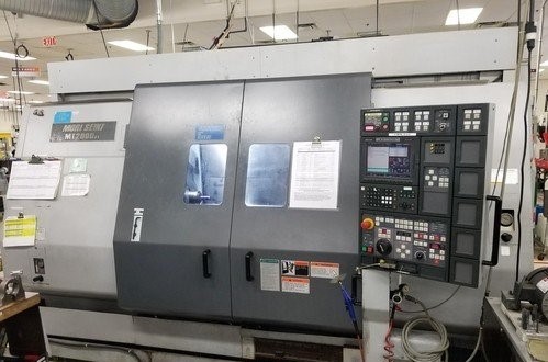
Smart Buyer’s Guide: How to Choose the Right Pre-Owned, Used, Secondhand, Surplus CNC Equipment Before Purchasing MORI SEIKI MT2000α1S CNC MultiTasking Turn-Mill Center made in Japan
When you’re evaluating a used / surplus / secondhand Mori Seiki MT2000 α1S (or equivalent MT2000 series) multi-tasking turn-mill center, you’re dealing with a highly integrated, complex machine (lathe + milling + live tooling + possible Y / B / C axes). Because failure or hidden wear in any subsystem can severely degrade performance (or become an economic burden), you need a rigorous inspection and evaluation framework. Below is a “Smart Buyer’s Guide” — a checklist, red flags, negotiation strategy, and special considerations — tailored for an MT2000-type machine.
What is “MT2000 α1S” / Typical Specs to Use as Benchmark
Before you inspect, it helps to know what the machine should be (or close to) so you can detect deviations, modifications, or misrepresentations.
From used listings and catalogs, here are representative specs for Mori Seiki MT2000 / MT2000α1S / “multitasking lathe” variants:
| Parameter | Typical / Listing Value | Notes / Source |
|---|---|---|
| Swing over bed / max swing | ~ 33.4″ (≈ 848 mm) | used Machinery listing |
| Maximum turning diameter (cutting) | ~ 21.6″ (≈ 548–550 mm) | |
| Distance between centers / turning length | ~ 50.5″ (≈ 1,280 mm) | |
| Spindle bore / bar capacity | ~ 2.99″ (~ 75.9 mm) bore; ~ 2.5″ (~ 63.5 mm) bar capacity | |
| Main spindle speed | ~ 4,500 rpm | |
| Sub-spindle / second spindle speed | ~ 6,000 rpm | |
| ATC / tool change (multitasking / milling) | e.g. 120 tools in one listing | |
| Milling head / B-axis, Y-axis capability | Many MT2000 machines include a B-axis / live tooling / Y-axis milling head | |
| Control | Mori / Fanuc (e.g. MSG-501 / MSC-501 control) in listings | |
| Machine weight & footprint | Very large machines (tens of thousands of lbs) | Implicit in listings; see “Weight 26,400 lbs” in one listing |
Note: These are “typical / advertised” values. Actual machine you inspect may deviate (due to modifications, wear, retrofits). Use them as comparison baselines.
Given the integrated nature (turning + milling + multi-axis capability), you’ll want to inspect all subsystems — lathe subsystems, milling / live-tooling, rotary axes (if present), control & software, auxiliary systems, and structural integrity.
Inspection & Evaluation Checklist
Below is a detailed checklist broken into key subsystems and areas. Use this both during remote review (photos / video / documentation) and in a thorough on-site inspection (with measurement tools, ideally with a technical expert).
| Subsystem / Domain | What to Inspect / Test | Why / Risk | Acceptable vs. Red Flag Indicators |
|---|---|---|---|
| 1. Application & Part Fit / Envelope | • Verify that your intended workpieces (length, diameter, fixturing) will fit within the machine’s turning envelope, milling head reach, clearance zones, tool interference. • Check whether your machining strategy (turning + milling, Y-axis features, B-axis rotation, etc.) is supported by this machine’s configuration. • Check tool reach / collision zones of live tools / milling head in all orientations. • Check whether control / CAM / postprocessor systems you plan to use are compatible with the machine’s control (e.g. MSG-501 or other). | Even a mechanically flawless machine is worthless if it cannot physically or kinematically make your intended parts. If certain regions are unreachable or cause collisions, you lose usable work area or need complex workarounds. | If your parts and fixturing geometries can be validated to work without interference / reach problems, that’s good. If you find interference, “blind spots,” or unreachable features, that may disqualify the machine (or require you to accept significant machining compromises). |
| 2. Documentation, History & Modifications | • Request full maintenance / repair logs (spindle rebuilds, axis repairs, head replacement, control upgrades). • Request original electrical schematics, hydraulic / pneumatic diagrams, lubrication diagrams, wiring plans. • Ask for history of crashes, collisions, overloads, axis limits hits, or collisions between spindle head and tool / workpiece. • Ask for software / control version history, backups of parameters, macro programs, and whether any retrofits or modifications were done (e.g. replaced spindle, aftermarket electronics). • Ask for parts lists and supplier or spare parts included. | A machine with a well-documented history is less risky: you can see what major components have already been replaced, approximately how many hours are on them, and where wear has occurred. Hidden or undocumented modifications can cause compatibility, reliability, or spare-parts issues. | Full, coherent logs, documented part replacements, and transparency are positive. Missing, fragmented, or suspiciously edited records are red flags. Any hidden / undocumented retrofits should be deeply investigated. |
| 3. Structural / External Condition | • Inspect castings, base, column, saddle (if present), and major structural members for cracks, weld repairs, visible distortion, or signs of foundation stress. • Examine machine covers, guard panels, way covers, bellows, shrouds for damage, misalignment, missing parts, corrosion. • Check for coolant, oil, hydraulic leaks on visible surfaces, around seals, joints, axes. • Check alignment of visible surfaces: table flatness, faceplates, axis rails for obvious warpage or misalignment. • Evaluate whether prior foundation movement or leveling corrections were done (look for patching, shimmed plates, anchor bolt evidence). | Structural geometry is mission-critical for multi-functions: any twist, sag, or distortion in major structure degrades accuracy under load. Repairing structural defects is extremely expensive and risky. | Minor cosmetic damage, paint wear, non-critical surface defects are tolerable. But visible cracks, heavy welds, significant warping, or foundation evidence of movement are red flags. |
| 4. Spindle(s) & Bearing Systems (Main, Sub, Live-Tooling) | • Run the main spindle (no load) across its rpm range (low to high), listening/feeling for noise, vibration, whine, knock. • Let it run for some time; check for hotspots or uneven heating on spindle housing. • Measure spindle runout (taper to nose) with a high-precision indicator and test bar. • If sub spindle is present, perform same tests on sub spindle. • If live milling / B-axis spindle exists, run it and test for noise, vibration, torque delivery, runout. • Ask for history of spindle or bearing rebuilds (dates, hours since) for main, sub, and live tools. • If there is through-spindle coolant (TSC), test for flow / pressure integrity under load. | The spindles (main, sub, milling) are among the costliest components. Any significant bearing wear, vibration, or misalignment will degrade part precision, shorten tool life, and often require expensive repair or replacement. | Quiet, smooth, within tolerance runout, moderate heat rise = acceptable. Excessive noise, vibration, heat, or out-of-spec runout = serious concern or deal breaker. |
| 5. Axis Motion / Guideways / Ball Screws / Backlash | • Jog all linear axes (turning axes, cross slide, milling axes, etc.) across full travel, both slow and faster speeds, and feel for stiction, binding, roughness, or jerkiness. • Use indicators to measure backlash (lost motion) in each axis at multiple positions. • Inspect guideway surfaces for wear, scoring, corrosion, nicks, chips, pitting. • Inspect way covers, wipers, seals for condition (intact, not torn, dragging). • Inspect ball screws / nuts / linear drives: feel for axial play, listen/feel for roughness, check for signs of wear or pitting. • Check the lubrication (grease / oil) delivery lines, metering valves, clogs, leak points. | Wear or damage in linear axes degrade repeatability, accuracy, finish quality, and may cause serious geometric drift. Refurbishing or replacing these components is expensive and labor-intensive. | Smooth motion, low, consistent backlash, minimal visible wear = acceptable. Binding, jump, excessive backlash, visible wear or scoring = red flag. |
| 6. Rotary / B-axis / Live Tool / Milling Head / Multi-Axis Mechanisms | • For B-axis / rotary head: command full rotation through range (positive and negative), check for smoothness, no binding or stiction, and accuracy of indexing. • Rotate and re-measure: pick a reference point, rotate, and check for positional shift to detect misalignment or index error. • Command combinations (turning + milling) to test simultaneous axis motion under idle or light load. • Check head/tool orientation locking (stiffness) under extra load. • Inspect gear trains, coupling joints, bearings in the milling axis / rotational head for wear or looseness. • If the machine includes a C-axis / Y-axis over the turret or live tools, test them similarly. | The multi-axis / milling subsystems often suffer from wear, backlash, thermal drift, or misalignment because they are mechanically more complex. Any looseness or error here directly degrades multi-process precision. | Smooth, accurate, low error, consistent indexing = acceptable. Stiction, play, drift, index misalignment, looseness = serious red flags. |
| 7. Tool Changer / ATC / Tool Magazine / Tool Handling | • Cycle the ATC through many tool changes (with tools of varying size/length) and monitor for hesitation, misloads, collisions, mis-indexing or errors. • Check the tool clamp / release mechanism for slippage or wear. • Inspect magazine rails, pockets, sensors, drive systems for wear, corrosion, misalignment. • After tool change, measure tool offset repeatability (i.e. whether tool tip offset is consistent). • If the machine uses tool pre-setters, inspect their accuracy and condition. | A worn or malfunctioning ATC reduces throughput, causes tool-change errors / collisions, and increases downtime. ATC repairs or part replacements are non-trivial. | Reliable, repeatable, many cycles with no error = good. Misloads, hesitation, sensor faults, worn pockets = red flags. |
| 8. Control System, Electronics, Wiring & Diagnostics | • Power-on the control (e.g. MSG-501 or equivalent), navigate through menus, view system diagnostics, error logs, alarm history. • Test axis motion commands, combined axis motion, live-tool calls, sub spindle control, etc. • Check data transfer ports (USB, network, serial), backup/restore functions, parameter read/write. • Inspect wiring harnesses, connectors, terminal blocks: look for corrosion, frayed wires, discoloration, loose connections. • Open control cabinet (if permitted) to inspect drive electronics (servo drives, power supplies, I/O boards), cooling fans, dust accumulation, burnt components or bulging capacitors. • Ask about spare electronics (replacement boards, modules) availability. | Even a mechanically sound machine is useless if control / electronics fail. Older machines often suffer from control obsolescence, failed boards, connector fatigue, or wiring issues. | If control is stable, responsive, all axes operate cleanly, no alarming logs = acceptable. If control crashes, boards missing/damaged, wiring issues, or control is obsolete (no spare parts) = high risk. |
| 9. Auxiliary & Support Systems | • Coolant / lubricant systems: test pumps, pipes, filters, flow, leakage, clogging. • Spray / mist / flood coolant performance, pressure and stability. • Lubrication / centralized grease / oil systems: inspect lines, valves, metering devices, leaks. • Chip management: conveyors, chip augers, chip trays, cleaning / chip removal paths. • Hydraulic / pneumatic systems (if present): cylinders, valves, air lines, pressure stability. • Safety systems: doors, interlocks, limit switches, emergency stop, guarding. • Ambient conditions: check facility wiring, power supply / grounding, cooling water, ventilation. | These “support systems” are often neglected and when they fail they can degrade reliability, cause downtime, or damage other parts. Repairing them after purchase is painful. | If all auxiliary functions work cleanly, no leaks, acceptable performance = acceptable. Pumps failing, leaks, broken valves, missing interlocks = red flags. |
| 10. Geometry, Calibration, Test Parts & Acceptance Testing | • Conduct geometric checks: squareness between axes, straightness over travel, alignment of spindle / axis centerlines, parallelism, flatness of relevant surfaces. • Run representative test parts (that include turning + milling features) across full envelope, including through multi-axis moves. Then measure critical dimensions, surface finishes, and check deviations. • Run at extremes of travel to see whether performance degrades away from center. • Warm up the machine (run motions or idle) and remeasure to observe thermal drift effects. • Perform repeated measurements over cycles / repeated jobs to test consistency and drift. • If possible, “rotate & re-measure” (turn part, re-fixture, re-measure) to detect systematic alignment errors. | The final arbiter is whether the machine can produce your required parts, tolerances, and finishes with consistency over time. Hidden geometric errors often only show up under real cuts. | If test parts and measurements fall within your tolerance window and remain stable over time, that is acceptable. If deviations, drift, or inconsistent performance appear, that is a serious concern. |
| 11. Spare Parts, Consumables & Support | • Ask which components (bearings, screws, spindles, seals, electronics modules) have been replaced, and when. • Investigate whether Mori Seiki (or successor / third-party) still support this model’s parts. • Ask for pricing & lead times for critical spares (spindle bearings, servo drives, control boards, rotational bearings, seals). • Ensure the seller can provide or include some spare consumables (filters, seals, belts, wipers). • Confirm whether software / firmware updates, patches, or support are still available. | A beautiful machine is worthless if you can’t replace a failed board or bearing. Parts obsolescence is a key long-term risk. | If parts are available, reasonably priced, documented suppliers = acceptable. If parts are scarce, outdated, or vendor support is dead = major red flag. |
| 12. Total Cost Modeling & Negotiation Buffer | • Estimate cost of refurbishing identified defects or wear (spindle rebuild, straightening, guideway repair, electronic repair, calibration). • Estimate rigging, disassembly, transport, foundation prep, leveling, installation, alignment, testing. • Add contingency buffer (commonly 10–20 %) for unknown surprises. • Use observed defects as negotiation leverage. • Insist on acceptance tests / trial period / performance guarantees before final acceptance / payment. • Ensure contract includes transfer of all software, control backups, manuals, and spare parts if promised. | Many used, “cheap” machines become expensive after hidden costs. You need a buffer to absorb surprises. | If sum (purchase + refurb + install) is still within your ROI envelope, acceptable. If your margin is zero (or negative) after including all costs, reject or re-negotiate heavily. |
| 13. Expert Inspection / Third-Party Evaluation | • Bring an experienced machinist, metrology technician, or service engineer to assist with the inspection. • Use diagnostic tools if available: vibration analysis, thermal imaging, motor current traces, signal integrity checks. • Request high-resolution videos / motion demos, control logs, error histories. • Use a formal acceptance / inspection checklist / form to record all measurements and observations. | Experts often spot latent defects you (as a non-specialist) might miss. Their feedback is often worth the cost of inspection many times over. | If expert gives clean or manageable report = positive. If major issues, ambiguous defects, or “too many red flags,” request corrections or walk away. |
| 14. Contract, Acceptance Criteria & Guarantees | • Specify clear acceptance test parts, geometric tolerances, and testing procedures (turn + mill features). • Negotiate a trial / burn-in period (e.g. a few days or weeks) during which you can reject or renegotiate if performance is off. • Require the seller to deliver documentation: manuals, software backups, parameter files, parts / spares lists. • Include liability / recourse for hidden defects discovered within a defined period post-delivery. • Insist that the machine be delivered “as tested / inspected” condition, not “as-is without recourse.” | A well-structured contract is your safety net. Without it, you may get stuck with surprises after purchase. | If seller agrees to acceptance, trial, documentation handover, warranty conditions, it indicates confidence. If seller resists such terms or insists on “no returns / as-is,” treat as high risk. |
Special Considerations / Gotchas Specific to MT2000 & Multi-Tasking Turn/Mill Machines
Because the MT2000 α1S is a sophisticated hybrid (turn + mill + multiple axes), there are extra complexities and pitfalls you should be especially alert for:
- Cycle count vs “hours of operation”
- Live tooling, B-axis, tool changes, axis oscillations often see more wear per hour than simple turning axes. A machine with “low hours” but heavy tool / axis cycles may be more worn than it seems.
- Thermal stability & multi-axis drift
- Because the machine houses multiple subsystems (turn + mill), thermal effects will often be more complex. The intersection of turning and milling heat may induce distortions. Always warm-up sufficiently before geometric testing.
- Load coupling between axes
- During milling cuts while the lathe is engaged, the coupling of dynamic loads may reveal weaknesses (play, bending, compliance). Test combined axis motion under light simulated loads.
- Retrofitted or changed components
- Spindle, motors, control boards, or milling heads may have been replaced or retrofitted. Confirm the quality and compatibility of any non-original components, and check whether they match the rest of the system.
- Software / control macros & compatibility
- The control’s macro features, conversational programming features, or multi-axis synchronization modules may be old or unsupported. Ensure you have backups, compatibility, and the ability to update or replace the control if needed.
- Complex calibration / compensation overhead
- After installation, expect nontrivial time (and possibly external metrology services) to re-calibrate (turning axes, milling axes, B-axis, live tool calibration, geometric compensation). Budget for that time and cost.
- Spindle gearbox / torque delivery in mixed modes
- In turn / mill operations, torque, backlash, and rigidity in spindle drive under varying direction loads can stress gear trains and bearings. Evaluate how the machine handles load reversals, torque swings, and live-tool torque.
- Parts support / obsolescence for hybrid functions
- Spare parts for turning, but also for milling and rotational axes, tool heads, and control modules, may be harder to find. The more hybrid features, the more varied spare parts you need. Confirm support for all subsystems.
- Rigging, installation, and floor requirements
- These machines are heavy, tall, and bulky. Ensure your facility can handle disassembly, transport (crane capacity, floor load, ceiling height), and reassembly. Plan how the machine will be delivered, and whether you need to separate heavy modules.