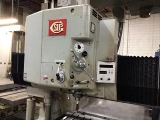
Smart Buyer’s Guide: How to Choose the Right Pre-Owned, Used, Secondhand, Surplus CNC Equipment Before Purchasing Sip 720 JIG Coordinated Hole Borer made in Switzerland
Below is a Smart Buyer’s Guide tailored for acquiring a used / surplus SIP 720 jig-boring / coherent “coordinated hole borer” (or equivalent high-precision jig / boring machine). Because jig borers are precision metrology machines rather than high-material removal mills, your inspection criteria must be more exacting. Use this as a framework (remote and on-site) to evaluate risk, condition, and value.
Things to Know Up Front: What Makes a SIP 720 Jig Borer Special
Before diving into the checklist, here are a few key facts and features of the SIP 720 (and general jig borer class machines) to help you calibrate your expectations and inspection thresholds:
- The SIP 720 CNC is typically marketed with large table/travel specs: e.g. X = 60″, Y = 40″, Z = 50″ (table-to-spindle nose) in used listings.
- It is designed more for precision hole coordinate bore / finish hole positioning than heavy material removal. Accuracy, rigidity, thermal stability, and motion smoothness are paramount.
- These machines often incorporate precision guideways, minute backlash compensation, fine spindle bearings, and high quality metrology / measuring feedback or error correction systems.
- Because of their precision focus, wear, small misalignments, and thermal drift affect performance much more severely than in standard machining centers.
- Some older SIP machines used optical measuring / feedback / hydroptic schemes (especially in SIP’s “Hydroptic” series) — those features may or may not be present in a SIP 720 variant.
Given that, your scrutiny should be intensive.
Inspection & Evaluation Checklist for a Used SIP 720 Jig Borer
You should apply this in phases:
- Remote screening (photos, videos, documentation)
- On-site inspection & measurement
- Test parts / acceptance testing
- Contract & warranties / guarantees
Below is a detailed breakdown of what to check, why it matters, what to bring, and red flags.
| Subsystem / Area | What to Inspect / Test | Why It Matters / What to Watch For | Acceptable vs Red Flag / Notes |
|---|---|---|---|
| 1. Fit & Suitability for Your Use | • Verify your workpiece size, fixture dimensions, and hole patterns can be accommodated within the SIP 720’s travel envelope (X, Y, Z). • Check whether your required hole tolerances and positions are within what a machine like this can deliver. • Confirm whether the candidate has all the axes / features you need (e.g. ability to bore + drill + mill in a coordinated fashion). • Confirm compatibility of control (CNC, interpolation, coordinate bore features) with your programming / CAD / CAM environment. | A jig borer is only useful if it can physically reach and hold the features you need. The control must support coordinate hole pattern interpolation and precise feedback. | Acceptable: your representative test geometry can be fitted and programmed; required features are present. Red flag: missing axes or travel, inability to program required patterns, limited strokes. |
| 2. Documentation, History & Maintenance Records | • Ask for full maintenance logs, service history, rebuilds, alignment checks, bearing replacements. • Request original and revised mechanical, electrical, wiring, hydraulics (if any), and lubrication schematics. • Ask about crash / overload events, or past collisions or damage. • Ask for control parameter backups, calibration maps, error compensation data. • Ask what consumables or high-wear parts have been replaced (e.g. spindle bearings, linear guides). | Good documentation gives insight into how “worked” the machine is, what components have life remaining, and what hidden risks remain. Missing logs often conceal serious wear. | Acceptable: consistent logs, major past repairs documented, control data preserved. Red flag: no logs, vague claims, missing control backups, unknown component history. |
| 3. Visual & Structural Inspection | • Examine the machine’s frame, columns, bridges (if any) for cracks, straightness, distortions, welds, signs of foundation shifting. • Check the machine’s base, table, slideways, covers, guards, doors, and way covers for damage, corrosion, missing parts. • Look for coolant, oil, or lubricant leaks at seals, transitions, bellows. • Check for rust, pitting, or flaking on visible surfaces. • Review how the machine has been stored or sheltered (moisture damage, dust). | Structural integrity is essential in a precision borer: any twist, warp, or damage degrades accuracy. External condition often reflects internal care. | Acceptable: straight, intact castings, minor cosmetic wear. Red flags: cracks, weld repairs in critical members, sagging bed, misaligned structure, heavy corrosion. |
| 4. Spindle & Bearing System | • Run the spindle (no load) across rpm range (low, mid, high). Listen/feel for noise, vibration, hum, chatter. • Let it run for time and check for localized heating or hotspots. • Use a high-quality test bar / gauge and dial indicator to measure spindle runout (taper to nose) in multiple positions. • Ask whether spindle bearings (or spindle itself) were rebuilt or replaced; get hours since. • If the spindle is minimal or has cooling / temperature stabilization, test its stability. | The spindle is one of the highest-risk, highest-cost failure points in a jig borer. Bearing wear or misalignment directly degrades hole accuracy. | Acceptable: quiet, smooth operation, runout within tight spec, modest heating. Red flags: knocking, vibration, high temperature, runout too large, evidence of bearing play. |
| 5. Guideways, Table Motion, Ball Screws / Drives | • Move the table / axes (X, Y, Z) manually / via CNC to full travel, observing for binding, stiction, roughness, for “notches.” • Map backlash / lost motion in axes (preferably at multiple travel positions). • Use a dial test indicator and mapping grid (i.e. move table under indicator at multiple points) to assess straightness / wear of guideways. • Inspect the way surfaces / guideways for scoring, pitting, chipped edges, galling. • Check the condition and sealing of wipers, way covers, bellows, and debris seals. • Inspect ball screws / drive nuts or drives (if any) for play, smoothness, wear. • Check lubrication lines, metering, clogging, leaks, or starvation zones. • In a forum discussion about SIP jig borers, users emphasize checking how much wear is present on the ways; also to check spindle-to-table runout, and smoothness of motion across the full stroke. | Precision in hole positioning depends heavily on the integrity of table and guide motion. Wear or backlash here is fatal to coordinate bore performance. | Acceptable: smooth, linear motion, minimal backlash, minimal wear. Red flags: binding, roughness, varying backlash, visible wear/damage on guides, large deviations in mapping. |
| 6. Control, Electronics, Feedback Systems | • Power up the control, inspect screens, menus, diagnostics, error logs. • Command axis moves, interpolation, coordinate hole cycles (if possible) to test multi-axis movement. • Test the system’s ability to load, edit, and run programs. • Check communication / I/O (USB, network, backup / restore) for parameter memory integrity. • Inspect wiring harnesses, connectors, terminal blocks, signs of wear / corrosion. • Open control / drive cabinets (if allowed) and inspect servo or motor drive electronics, I/O boards, power supplies, cooling fans, and check for burnt boards or components. • If the machine uses measuring feedback (e.g. linear scales, encoders, optical systems), verify they are functional / calibrated. • Ask whether spare control / electronics modules are still available. | Even a mechanically perfect jig borer is useless if the control or electronics fail or suffer drift or calibration errors. Systems with measuring feedback or compensation are especially vulnerable. | Acceptable: stable control, no alarms, responsive motion, clean wiring. Red flags: missing or failing boards, repeated errors, wiring damage, control obsolescence with no spare support. |
| 7. Metrology / Calibration / Test Parts | • Perform geometric checks: squareness in X-Y, linearity over table motion, flatness / parallelism. • Use gauge blocks / master standards: mount a precision datum in the spindle, use the table to map a grid of known points, check deviations. • Run a test part (or holes) with coordinate hole cycles, then measure whether holes are exactly in programmed positions (repeatability). • Operate the machine for some time (warming it up), then retest to detect thermal drift or drift over time. • Repeat cycles to detect cumulative error or drift. • Compare opposite-direction moves to detect hysteresis or backlash effect. | The whole point of a jig borer is to locate holes with extremely tight positional accuracy; only metrology tests can validate whether the machine can perform as needed. | Acceptable: deviations within your tolerance window, stable over time. Red flags: systematic shifts, drift, inconsistent results, positional error outside your spec. |
| 8. Auxiliary Systems, Cooling, Lubrication & Debris Management | • Test the machine’s lubrication / oiling / grease systems: are they functioning and consistently delivering lubricant to where needed? • Check coolant / flood / spray systems (if any) for plumbing, pump, pressure, leaks, contamination. • Inspect chip / debris removal, table housekeeping, guarding, way wipers. • Examine sealing systems, bellows, covers, to ensure debris isn’t infiltrating critical surfaces. • Check the machine’s environment: is it protected from temperature swings, cleanliness, vibration, and ambient contaminants? • Inspect the machine’s power, grounding, electrical protection, expansion joints, and noise suppression. | A contaminant or lubrication failure can degrade accuracy over time. Keeping the precision surfaces clean and well-lubricated is essential. | Acceptable: auxiliary systems fully operational, no leaks, good coverage, environment is stable. Red flags: lubrication failures, leaks, no sealing, poor debris control, unstable ambient conditions. |
| 9. Spare Parts, Consumables & Support | • Ask what high-wear parts (spindle bearings, guideways, drive mechanisms, electronics) have been replaced and when. • Investigate whether SIP or aftermarket sources still supply replacement parts or subassemblies for the 720 model. • Get cost and lead time estimates for critical components (e.g. spindle bearings, guideways, control boards). • Ask if the seller can supply spare governing parts, calibration standards, or metrology aids. • Confirm whether software / firmware / calibration patches are still supported and whether calibration files can be backed up / transferred. | Precision machines are only as good as their maintainability. If you can’t get spares or calibration support, long-term downtime becomes a risk. | Acceptable: many spare parts still available, supplier documentation, manageable cost. Red flags: parts obsolete, extremely long lead times, no local support, calibration modules lost. |
| 10. Cost Modeling, Risk Buffer & Negotiation | • Estimate refurbishment costs (spindle service, guideway rework, control repair, calibration). • Estimate transport, rigging, installation, calibration, test run setup. • Add a contingency buffer (10–20 %) for hidden issues. • Use documented defects from inspection as negotiation leverage. • Insist on a trial / acceptance period, with final acceptance contingent on metrology performance. • Hold back part of payment until acceptance / test satisfaction. • Ensure contract includes full transfer of documentation (maintenance logs, calibration files, wiring, schematics). | Many “cheap” precision machines become expensive once hidden rework and calibration costs are included. You need margin to absorb surprises. | Acceptable: total landed and refurbished cost still yields ROI. Red flag: margin is nil or negative, seller resists trial or inspection rights. |
| 11. Expert / Metrology Inspection | • Bring a metrology / machine inspection expert (or lab) to assist in setting up measurement tests, verifying mapping, interpreting deviations. • Use high-precision measurement tools (granite squares, interferometers, calibrators, laser trackers) for check-out. • Request full motion videos, control logs, error maps, calibration records ahead of time. • Use a structured acceptance checklist / measurement plan during inspection. | Expert measurement often reveals subtle errors you may not see. Their report can save you thousands of dollars in hidden cost. | Acceptable: expert finds errors within tolerance or remediable. Red flag: expert finds unrecoverable errors beyond budget or too many risk flags. |
| 12. Contract / Guarantees / Acceptance Terms | • Insist on a formal acceptance test in your environment (test parts, metrology grid checks) before you sign off. • Negotiate a trial / burn-in period (days to weeks) during which the seller is responsible for failures. • Require the seller to deliver all documentation: calibration maps, software backups, wiring, schematics, spare parts list. • Include clauses for post-delivery defects, warranty on critical systems (spindle, guidance, electronics). • Hold part of payment in escrow or retain a holdback until acceptance criteria are met. • State that machine must be delivered in “as inspected / tested” condition. | Because precision is so critical, you must protect yourself contractually. Otherwise you risk inheriting hidden deviations. | Acceptable: seller agrees to your acceptance and warranty terms. Red flag: seller refuses trial, insists “sold as-is no returns,” refuses to share calibration data. |
Additional Tips & Practical Considerations for SIP / Jig Borer Machines
- Thermal stability and drift
- Because the tolerances are very tight, temperature differences, thermal drift, and expansion can drastically affect accuracy. Let the machine and environment reach thermal equilibrium before measuring.
- Observe how the machine behavior changes after hours of operation (re-measure after warm-up).
- Mapping the table / motion errors
- One of the best checks is to map a grid of points (using a precision indicator or probe) across the table surface via the spindle, and record deviation from nominal. This mapping reveals deviations in guides, pitch errors, linearity or table bending under load.
- Spindle-centric aligning
- Check spindle-to-table perpendicularity and alignment. Use gauge blocks, test bars, and ensure that spindle movement is square to table axes.
- Check how well the machine can bore holes in opposing sides (mirror) or repositioned workpieces.
- Optical / measuring feedback systems
- If the machine has auxiliary measuring systems (scales, encoders, optical feedback), verify their calibration and health. Such systems are critical for maintaining long-term positional fidelity.
- Hardness / wear of ways
- Jig borers often rely on hardened and lapped ways; verify whether they’ve lost surface hardness or show plastic deformation — an indicator of abuse or overload.
- Vibration / stability of the foundation / base
- Since precision is key, the supporting foundation, mounts, and machine rigidity are critical. Ensure the base is stable, anchored and the environment is vibration controlled.
- Re-calibration requirement
- After transport / installation, the machine will invariably require recalibration, compensation tuning, and test runs. Budget time and cost for that.
- Long-term support and metrology crossover
- Because this class of machine is often maintained by metrology or precision machine shops, having a local metrology house or calibrator that understands jig borers is a plus.
- Check whether calibration references, gauge blocks, master standards for this machine are still available.
- Spare spindles, guideway salvage kits, electronics spares
- Try to negotiate inclusion of spare spindle bearings, guide liners, electronics cards, and calibration offsets. These can save you downtime in the future.