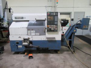

Smart Buyer’s Guide: How to Choose the Right Pre-Owned, Used, Secondhand, Surplus CNC Equipment Before Purchasing OKUMA LCC15 2S CNC Turning Center made in Japan
Here’s a Smart Buyer’s Guide you can use when evaluating a pre-owned / surplus / secondhand OKUMA LCC15-2S (or equivalent LCC15) CNC turning center. Because these machines are relatively compact but often feature twin turrets, multiple axes, and potentially sub-spindle or driven tools, hidden wear or defects can significantly degrade value. Use the checklist below to vet candidates thoroughly, negotiate wisely, and avoid expensive surprises.
I’ll start with what I found about the LCC15 family (benchmarks), then lay out a detailed inspection and evaluation framework, red flags, contract/negotiation tips, and special Okuma-specific caveats.
Benchmark / Typical Specs for the OKUMA LCC15-2S (Reference Baselines)
When inspecting a used machine, you want reference specs to compare what the machine should deliver vs. what it actually delivers (or claims). Below are some data gathered from used listings of LCC15-2S units. Use them as “expected ranges” rather than guaranteed values:
| Spec | Typical / Used Listing Value | Notes / Source |
|---|---|---|
| Maximum swing over saddle | ~ 17.71 in (≈ 450 mm) | The “saddle” swing is often less than bed swing; this gives you a usable diameter on the sliding ways. |
| Z-axis travel (main spindle) | ~ 12.60 in (≈ 320 mm) | This is the effective turning length (feed in Z) for the main spindle. |
| Max turning diameter | ~ 10.62 in (≈ 270 mm) | Some sources report 8.26 in (for internal diameter or limited use) |
| Turning length / between-centers | ~ 11.02 in (≈ 280 mm) | Some listings show length 280 mm or 320 mm in certain configurations |
| Spindle bore / bar capacity | ~ 2.44 in (≈ 62 mm) | The interior bore capacity of the spindle to accept stock. |
| Spindle speed range | 35 – 4,200 rpm | In used machines, this is commonly cited. |
| Number of turrets / tool stations | Twin (2) turrets, 12 + 8 positions in some listings | One listing: upper turret 12, lower 8 positions. |
| Rapid traverse / feed rates | Rapid on Z ~ 787 ipm (~20 m/min) | For such a machine, fast rapid motion is important for cycle time. |
| Machine weight / size | ~ 3,800 kg | One Italian listing gives 3,800 kg for a 2003 machine. |
| Ceilings / footprint / swing envelopes | Some reference: turning “turn table diameter 200 mm, turning length 320 mm” t | Useful for gauging space requirements. |
These typical values are benchmarks — your candidate may deviate slightly due to optional features, wear, modifications, or previous rebuilds. But significant deviation downward (e.g. much less spindle bore, low travels) is a warning sign.
Inspection & Evaluation Checklist
Use the following checklist during both remote evaluation (photos, videos, documentation) and on-site inspection. Bring precision instruments (dial indicators, test bars, squares, gauge blocks, etc.) if possible, and ideally have a machinist or inspector accompany you.
Each item includes why it matters and what to watch for.
| Subsystem / Area | What to Check / Test | Why It Matters / Common Risks | Acceptable Conditions vs Red Flags |
|---|---|---|---|
| 1. Application / Fit to Your Parts | • Verify your part’s maximum diameter, length, and required features will physically fit (within swing, Z travel, and turret reach). • Check whether tool lengths, overhang, tool holders, and clearance zones will allow full motion without collisions. • Confirm whether the unit has the exact turret / tool-station configuration you need (e.g. 12x + 8x) and whether live tooling or driven tools are present (if needed). • Ensure that your programming environment / CAM / postprocessor can support this control version (OSP-7000L or equivalent) and any optional axes. | If your parts don’t physically fit, or tool interference is frequent, the machine will be unusable even if mechanically “good.” Missing or improper turret / tool options may require costly retrofits. | Acceptable: your critical parts run with margin in all axes, no interference. Red flags: collisions at extremes, insufficient tool reach, missing needed turret positions, or dramatically reduced travel. |
| 2. Documentation, History & Modifications | • Request full maintenance / service logs: spindle rebuilds, alignment checks, repairs. • Ask for original electrical, hydraulic (if used), lubrication, wiring, and mechanical drawings / schematics. • Ask for crash / collision history, overtravel incidents, or misuse. • Ask for records of part replacements (spindle bearings, screws, seals, motors). • Ask for software / control upgrade history, backups of parameters, macro programs, or custom modifications. | Good documentation helps you predict remaining useful life, spot replaced components, and understand how “worked” the machine has been. Hidden or undocumented mods often mean unexpected compatibility or reliability issues. | Acceptable: continuous, coherent logs; documentation of major repairs or replacements; control backups handed over. Red flags: missing logs, vague “as-is” statements, refusal to share schematics, undocumented retrofits. |
| 3. Structural / External Condition | • Visually inspect bed, saddle, headstock, tailstock, turret frames, and castings for cracks, weld repairs, distortions, or misalignment. • Check bed straightness, sag, or visible wear. • Examine covers, way covers, bellows, doors, guards — for dents, corrosion, misalignment. • Look for coolant / oil leaks, rust, stains near seals, axis transitions. • Examine base alignment, mounting / shimming, evidence of re-leveling or foundation shifting. | Structural defects or deformations impair alignment and accuracy. Repairs or welds in critical members often indicate past damage and may not restore rigidity fully. | Acceptable: straight, intact castings, minimal cosmetic damage. Red flags: cracks, rewelded sections, sagging or warped bed, misaligned structures. |
| 4. Spindle(s) & Bearing Health | • Run the main spindle (no load), through its rpm range (low, medium, high); listen/feel for noise, knocking, growl, vibration. • Let it run and then touch the housing to detect hotspots. • Use a test bar and dial indicator (or better metrology tool) to measure spindle runout (taper to nose). • Ask whether spindle bearings were ever replaced/rebuilt; obtain serials and hours since. • If sub-spindle or secondary axes exist (LCC15-2S is “2S” version), similarly test those spindles. • If the spindle is coolant-through (if so equipped), test coolant flow, pressure, integrity of seals. | The spindle and its bearings are often among the most expensive repairs. Noise, vibration, or excessive runout often hint at bearing wear or damage. | Acceptable: smooth, quiet, minimal runout within spec, modest temperature rise. Red flags: knocking, vibration, elevated heat, runout beyond tolerance, looseness or evident bearing play. |
| 5. Motion Systems: Guideways, Ball Screws, Backlash | • Jog each axis (X, Z, and any others if present) across full travel both slowly and rapidly — check for binding, stiction, jumps, or rough zones. • Use dial indicators or other precision tools to measure backlash / lost motion in each axis at various points in travel. • Inspect guideway surfaces for wear, pitting, scoring, corrosion, or chips. • Check way covers, wipers, seals, and bellows for integrity and sealing. • Inspect ball screws, nuts, and drive interfaces for axial play, pitting, wear, binding, or irregular motion. • Verify lubrication / greasing / oil feed lines, metering units, blockages or leaks. | Accurate, repeatable motion depends heavily on the integrity of guideways and screws. Wear here directly degrades part accuracy, repeatability, and surface finish. Repair or replacement is expensive. | Acceptable: smooth, consistent movement; backlash within acceptable spec; surfaces in good shape. Red flags: binding, rough transitions, high or inconsistent backlash, visible wear or damage. |
| 6. Turret(s), Tool Changer, Tool Holding | • Cycle the turrets / tool changers through all tool positions (with varying tool lengths/weights) and monitor for hesitation, misloads, collisions, indexing issues. • Check clamp / release mechanisms for wear, slippage, binding. • Inspect turret drive, indexing cams, sensors, pocket alignment, pocket wear or damage. • After tool change, measure consistency / repeatability of tool tip offsets. • If driven tools / live tooling are present, test power delivery, torque under moderate load, runout, alignment. | Tool changer / turret problems cause downtime, scrap, and can damage parts. Wear in turret indexing or clamping mechanisms is often costly. | Acceptable: smooth, reliable indexing and tool changes; repeatable tool offsets. Red flags: tool misloads, hesitation, inconsistent offsets, worn pockets, turret slop. |
| 7. Control System, Electronics & Wiring | • Power up control (OSP-7000L or equivalent), navigate menus, inspect error / alarm logs, diagnostic screens. • Execute axis movement commands, load test programs, run dry cycles. • Test data transfer (USB, network, serial) and ability to backup/restore parameters. • Inspect wiring harnesses, connectors, terminal blocks for corrosion, loose wires, discoloration, damaged insulation. • Open control/drive cabinets (if permitted) to inspect servo drives, I/O modules, power supplies, cooling fans, dust, burnt components. • Ask whether replacement control / electronics modules are available and whether the existing control is still supported. | Even a mechanically perfect machine is useless if the control or electronics are failing or unserviceable. Many older electronics (I/O boards, drives) are common points of failure. | Acceptable: stable, no alarm logs, responsive commands, clean wiring. Red flags: frequent control crashes, missing or burnt boards, wiring issues, obsolete control with no spare parts. |
| 8. Auxiliary & Support Systems | • Coolant system: pump, piping, filters, flow, leakage, contamination. • Lubrication / greasing / oil distribution: lines, metering units, valves, leaks or blockages. • Chip handling: conveyors, chip bins, augers, chip removal paths. • Hydraulic / pneumatic systems (if any): valves, hoses, cylinders, leaks. • Safety features: doors, interlocks, limit switches, emergency stops. • Inspect machine bed for built-in coolant tanks or sump, check for sludge, rust, contaminant accumulation. • Check facility compatibility: power supply, grounding, cooling water, floor loading, crane / rigging. | Failures in support systems can render the machine unusable or reduce reliability dramatically. Cleaning, repairing, or replacing them after purchase is often a headache. | Acceptable: all auxiliary systems working, no leaks, proper flow. Red flags: failed or noisy pumps, leaks, broken interlocks, wiring damage, facility mismatches. |
| 9. Geometry, Calibration & Test Part / Acceptance Testing | • Perform geometric checks: squareness (X–Z axes), alignment of spindle axis relative to carriage, straightness, parallelism of axes. • Run representative test parts (preferably ones exercising most axes / features), measure critical dimensions, surface finish, repeatability. • Test near the ends of travel to detect drop-off in accuracy. • Warm up the machine (run idle or with motion) and re-measure to detect thermal drift. • Repeat part runs over multiple cycles to assess stability and drift over time. • Use back-and-forth motion / reverse path checks to detect hysteresis or lost motion. | The ultimate criterion is whether the machine can reliably make your parts within tolerance. Hidden misalignment, drift, or geometric error often only shows under load or over time. | Acceptable: parts within tolerance, stable, minimal drift. Red flags: deviations beyond tolerance, drift over time, inconsistent performance, positional error that correlates with axis position. |
| 10. Spare Parts, Consumables & Support | • Ask what critical components (bearings, screws, seals, control modules) have been replaced and when. • Investigate whether Okuma (or authorized dealers / local resellers) still supply parts for this model. • Request pricing and lead times for critical spare parts (spindle bearings, drive boards, turret parts, seals). • Ask if the seller can include consumables / spare parts (filters, wipers, seals) with the machine. • Inquire about software / control updates, patches, or support availability. | Even a “perfect” used machine is worthless if you cannot keep it running. Parts obsolescence is a serious long-term risk. | Acceptable: parts are available (or reasonable aftermarket), documented suppliers. Red flags: parts obsolete, extremely long lead times, no local support. |
| 11. Total Cost Estimation & Negotiation Buffer | • Estimate refurbishing / repair costs for observed defects (spindle, guides, turret, control) and add to purchase cost. • Estimate transport, rigging, disassembly/assembly, foundation, leveling, utilities, calibration. • Add contingency (10–20 %) for unexpected defects. • Use documented defects as negotiation leverage. • Insist on acceptance tests (test parts, geometric checks) before final acceptance / payment. • Include contract terms for delivery condition, documentation, spare parts, liability for hidden defects. | Many used machines appear cheap until hidden repair, alignment, or control issues appear. You need margin to absorb surprises. | Acceptable: total outlay (purchase + repair + install) still gives headroom vs alternative machines. Red flag: your margin is zero or negative after all costs, seller refuses testing or guarantee. |
| 12. Expert / Third-Party Inspection | • If feasible, bring a machinist, service technician, or metrology/inspection expert to assist. • Use diagnostic tools (vibration analyzer, thermal imaging, current trace) if available. • Ask for motion / demo videos, error logs, control diagnostics ahead of time. • Use a formal inspection checklist to record all measurements and observations. | An expert often spots defects or risk areas you might miss; their feedback often pays for the inspection cost. | Acceptable: expert gives manageable report (with caveats) or minor issues. Red flag: major defects unearthed or ambiguous condition that cannot be mitigated. |
| 13. Contract, Guarantees & Acceptance Terms | • Define clear acceptance tests (sample part runs, geometric tolerances) as a condition before final acceptance. • Negotiate a trial or “burn-in” period (days/weeks) during which you can reject or raise issues. • Require the seller to hand over all documentation: manuals, wiring, schematics, control backups, parts lists. • Include clauses for hidden defect liability, repair obligations, holdbacks until acceptance. • Ensure the machine is delivered in “as tested / inspected” condition, not vague “as-is.” | A good contract is your protection. Without it, you may be stuck with unseen defects. | Acceptable: seller agrees to your acceptance criteria, trial, documentation. Red flag: seller resists inspection, refuses trial/guarantee, or insists “final sale, as-is, no returns.” |
Special Considerations / Okuma-Specific Notes for LCC / Small Okuma Lathes
When dealing with Okuma, especially smaller lathes like the LCC / LB series, here are extra tips and pitfalls to watch out for:
- Gearbox / integral headstock design
- The small Okuma lathes (LB / LCC / Cadet series) sometimes use a gearbox integral to the headstock. In a forum discussion, an Okuma user noted: > “These Okumas were a bit unique, with a gearbox integral to the headstock.”
- That gearbox, and its condition (gears, backlash) can be a delicate wear point. Verify gear noise, backlash, and any history of gearbox overhaul.
- Box way / inclined bed designs
- Many Okuma small lathes use box ways or slanted bed designs for rigidity. These ways are intended to maintain alignment under load. If the ways are worn, the machine may lose positional accuracy or show variation under load.
- Evaluate how evenly the wear is distributed; heavily worn ways (unevenly) are very expensive to repair.
- Integrated coolant sump / base design
- Some Okuma lathe castings integrate the coolant tank into the base/frame. This is great for structural compactness but makes cleaning, de-sludging, or repairing leaks more difficult. (One forum user: “the coolant tank is integral to the base, makes for hell to clean out.”)
- Check for rust, sludge, or rust perforation inside the base, as these can go unnoticed but become serious.
- Drive / coupling to ballscrew (belt coupling, etc.)
- In some smaller Okuma lathes, servo motors are coupled to ball screws via belts (or flexible couplings). Over time, belts stretch, couplings wear, leading to positioning error. One forum comment mentions using belts in servo-to-screw coupling in smaller Okumas.
- Inspect belt tension, play, belt condition, alignment, and coupling parts.
- Control / support for the OSP / control generation
- Many used LCC15 machines are equipped with Okuma OSP-7000L or OSP controls. One listing: 1997 LCC15-2S with OSP-7000L, twin turrets, collet chuck.
- Confirm the control version, software patches, and whether modules / spare cards are still available.
- Turret synchronization & backlash
- Because some LCC15 versions have twin turrets, synchronization (especially in off-axis milling or synchronized turning) is critical. Any misalignment or excessive backlash in turret indexing can degrade part accuracy.
- Test for backlash or play between turret axes and verify turret indexing repeatability under load.
- Pay more attention to small deviations
- In large machines, certain tolerances / error magnitudes may be acceptable. In a compact turning center, even small misalignments or deviations are magnified proportionally. Be stricter in your tolerance thresholds.
- Spare parts for smaller / less common models
- Because LCC is a specialized or less common model relative to larger Okuma lines, some parts (spindle bearings, control I/O boards, turrets) might have limited availability. Before purchase, verify spare parts availability locally or regionally.
- Cycle count / turret usage wear
- Turret indexing cycles often outpace linear axis hours. Even if the machine has moderate “hours,” if turret cycles are high, the turret drive might be heavily worn.