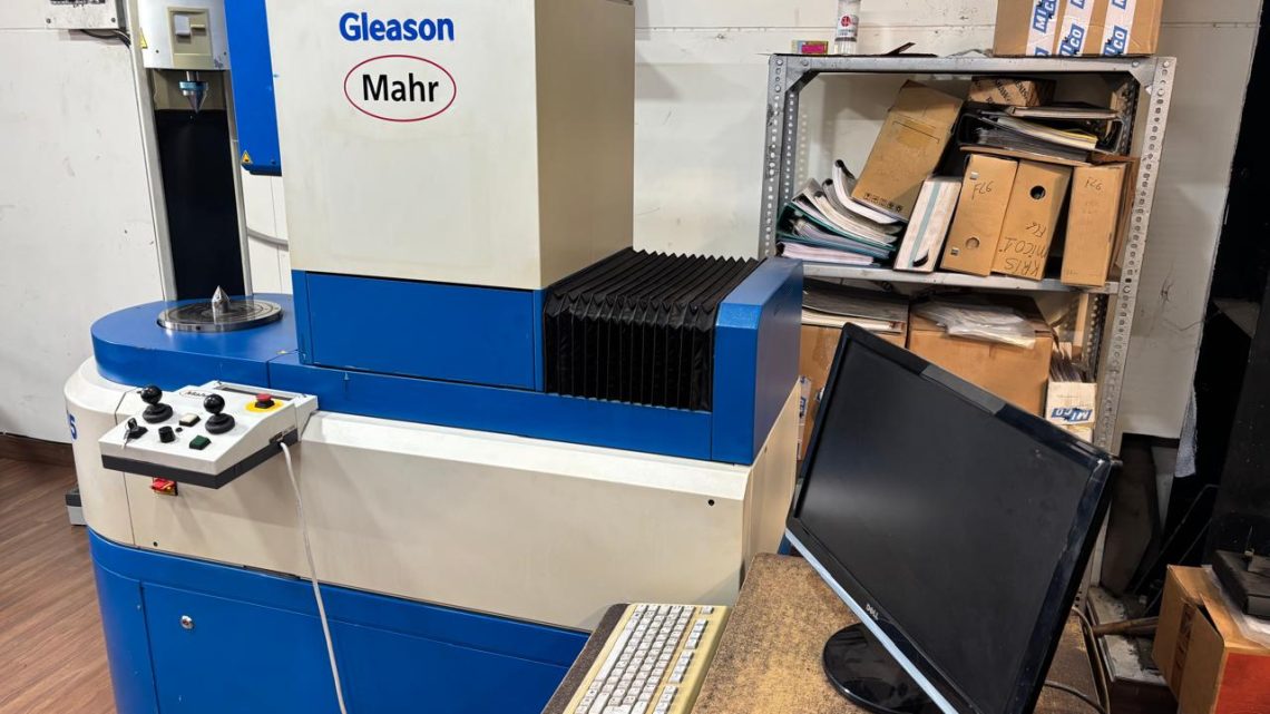
Smart Buyer’s Guide: How to Choose the Right Pre-Owned, Used, Secondhand, Surplus CNC Equipment Before Purchasing Gleason MAHR GMX 275 CNC Gear Measurement Tester Machine made in Germany
Below is a Smart Buyer’s Guide for evaluating a pre-owned / surplus Gleason / Mahr “GMX 275 / GMX 275C / GMX 275 W / GMX series” CNC gear measurement / metrology machine (sometimes called “GMX 275” or “Gleason-Mahr GMX 275 / GMX 275C / GMX W”) (i.e. a high-precision gear / form / contour tester). Because these machines are precision metrology instruments, their “error budget” is very tight and even small defects or drift can ruin their usefulness. So the diligence must be higher than for a general CNC machining center.
I’ll first lay out what is known about the GMX 275 (capabilities, tolerances, constraints) to set your reference, and then walk through what to check, measure, test, and negotiate. Finally, I’ll flag typical “deal breakers” and risk mitigations.
1. What You Should Know: Reference Specs & Capabilities of GMX 275 / GMX Series
To know what “good” looks like, here are data from publicly available catalogs and datasheets of Mahr / Gleason-Mahr GMX gear measurement machines. These set the benchmark that a used machine should approximate (or be capable of being restored to).
- The Gleason-Mahr / MarGear GMX 275 is a universal (cylindrical / bevel) gear measuring center capable of measuring external & internal gears, cutting tools (hobs, shavers, cutters), helical / spur / conical / bevel gears.
- Key travel / measurement ranges:
• X travel ~ 180 mm
• Y travel ~ 150 mm
• Z travel ~ 320 mm
• Maximum cylindrical gear diameter ~ 275 mm
• Maximum length (distance between centers) for test pieces (for cylindrical) ~ 450 mm in many implementations
• Max workpiece weight ~ 60 kg (some variations 80 kg by request) - Accuracy & tolerance:
• The machines are specified to Accuracy Class I for gear measurements, in conformity with VDI / VDE 2612 / 2613 standards (Group 1) at 20 °C ± 2 °C ambient conditions.
• Example runout tolerances: axial runout deviation ~ 0.11 µm + 0.0008 µm/mm (measuring radius)
• Radial runout deviation (in table height) ≤ 0.11 µm in typical spec. - Rotary / C-axis / table / indexing:
• C-axis (rotary table) rotation 360°, with positioning and measuring speeds (e.g. 0.1 °/s to 120 °/s measuring, up to 180 °/s positioning)
• Table diameter ~ 240 mm for many GMX 275 versions - Other features / options:
• 3D scanning probes as standard or option (multi-axis probe arms)
• Option for tailstock / center supports for long shafts (up to ~ 700 mm) in some versions
• Active vibration damping systems in some configurations
• Software for gear measurement, form / contour / position / profile evaluation (MarWin / similar)
Given such tight tolerances, any mechanical, thermal, or electronic drift must be minimal for the machine to remain useful.
2. Pre-Inspection Information to Request from Seller / Broker
Before visiting the machine, obtain as many of these as possible. The better the information, the less risk of hidden surprises.
- Identification & Build Details
– Model / version: GMX 275, GMX 275C, GMX 275 W, or variant
– Serial number, build year, revision / firmware version
– Option list / configuration (which probes, whether tailstock, vibration damping, software options) - Usage History, Hours & Workload
– Number of measurement hours, count of workpieces measured
– Duty profile (light metrology use, production line throughput, intermittent use)
– Idle or downtime periods - Maintenance / Calibration / Service Records
– Records of major calibrations, axis realignment, spindle / rotary table overhauls
– Records of repairs (drive motors, encoders, probe systems)
– Preventive maintenance logs (lubrication, alignment checks, thermal monitoring) - Modifications, Repairs, Retrofitting
– Any retrofits (upgraded controller, probe system, axis motors)
– Any structural repairs (welds, replaced axis guideways)
– Changes from original probe / configuration - Documentation Provided / Missing
– Mechanical, electrical, wiring, schematic, drawing / parts lists
– Software, control manuals, parameter backups, calibration certificates
– Probe arm data, calibration masters, standards - Included Accessories / Spares
– Probe arms, extension probes, spare sensors, calibration rings, test masters
– Backup electronics modules, encoders, motor drives - Photos / Demo Videos
– Videos of machine in operation (axis moves, rotary indexing, probing)
– Close-up photos of mechanical axes, encoders, wiring, control cabinet - Environmental / Installation Details
– Room temperature control (metrology room requirements)
– Vibration isolation or damping environment
– Foundation, leveling, anchoring, floor stability - Reason for Sale / Current Condition
– Why is it being sold? Under-utilized, replaced, moved, broken?
– When last used, whether in working condition before shutdown
If the seller cannot provide good calibration / traceability records, that is a red flag.
3. On-Site Inspection & Detailed Mechanical / Structural Checks
When on site, you’ll have to inspect physical condition, axis mechanics, rotary table, probe systems, and electronics. Because the tolerances are in sub-micron ranges, every little defect matters.
A. Structural, Frame & Vibration / Stability
- Check the machine base, frame, support casting for cracks, distortion, signs of repair, warps.
- Inspect for solid, rigid mounting; check whether machine has been moved, re-leveled, or damaged.
- Examine shielding, covers, guarding for damage or missing parts.
- Check whether the machine sits rigidly, without external vibration coupling (floor vibrations, neighboring machines).
- If damping / anti-vibration systems exist, ensure they are functional or properly maintained.
B. Linear Axes / Guides / Carriage / Slideways
- Visually inspect guideways for wear, scratches, scoring, corrosion, pitting, dust ingress.
- Move axes (X, Y, Z) slowly and through full travel — sense for smoothness, stick-slip, binding, irregular friction.
- Reverse direction and measure backlash (small reverse moves, check deviation).
- Use a precise microscope / dial indicator / test gauge to check straightness of axis motion over travel.
- Check scale / encoder rails: clean, unscratched, correctly mounted, no play in mounting.
- Inspect lubrication system: oil / grease lines, bearings, seals, clean oil, filters.
- Check protection / wipers / wipers / covers for guideways — missing or damaged wipers degrade axes.
C. Rotary Table / C-Axis / Indexing Mechanism
- Run rotary table: rotate through full 360°, back and forth, check for vibration, misalignment, roughness.
- Use a precision roundness / runout indicator to measure radial and axial deviation of the table / spindle.
- Check indexing repeatability (go to same angle repeatedly) and accuracy (how close to commanded angle).
- Inspect couplings between rotary table motor and table; check for backlash, slop, lost motion.
- Inspect bearings or support in rotary axis for wear or looseness.
- Examine encoder or angular position feedback sensor for condition, cleanliness, shielding.
D. Probe / Measuring System, Sensors & Arms
- Inspect the probe / stylus system: check probe arms, pivots, mechanical joints for wear, play, looseness.
- Check electrical / signal cables from probe: shielding, insulation, connectors, routing.
- Check mounting of probe system, thermal drift, how probe is zeroed and referenced.
- Trigger probe in controlled tests to see response, noise, stability.
- If multi-axis scanning or probe head change is supported, test changeover / repositioning.
- Verify that sensor electronics (amplifiers, filters, signal conditioning) are working and stable.
E. Electrical / Control / Cabinets / Wiring
- Open control / electronics cabinets: inspect for dust, coolant ingress, corrosion, burn marks, discoloration, moisture.
- Check wiring harnesses, terminations, grounding, shielding, labels, strain reliefs.
- Inspect power supplies, servo drives, amplifier boards, encoders interface, signal boards.
- Check for module overheating, fan operation, clean heat sinks.
- Test that control system powers up cleanly, no error LEDs, no interlock faults.
- Check backup battery / memory retention of parameters / calibration constants.
F. Environmental Tests
- Check room temperature stability (metrology requires tight thermal control).
- Measure ambient temperature gradients, fluctuations, drafts near the machine.
- Check whether the machine will operate in its current location without interference from vibration (e.g., from other machines).
- If environmental isolation (temperature control, enclosure) is needed, see whether provisions exist.
4. Functional / Measurement & Accuracy Testing
This is the most critical part. A gear measurement machine must deliver precise results. Prepare calibration standards (e.g. master gears, rings, test standards) to test against.
- Baseline Calibration / Master Measurement
– Use a known master gear / calibration standard to verify that the machine reports known values within spec.
– Measure diameter, form, runout, tooth thickness, pitch, profile deviation etc., compare to certificate. - Repeatability & Reproducibility
– Re-measure the same gear / standard repeatedly (e.g. 5–10 runs), compute variation statistics.
– Move axes off, then come back, re-trigger probe, ensure consistency. - Full Gear Measurement Cycle
– Run a full measurement cycle of a real gear (spur / helical) across profile, lead, runout, tooth thickness, deviation, etc.
– Measure against expected tolerances; check whether any profile deviations exceed tolerance. - Chuck / Clamping Repeat Accuracy
– Remove and re-clamp same gear and measure again; see how much error is added by reclamping.
– Check mechanical centering (if manual) or computational correction (wobble correction) if supported. - Thermal / Warm-Up Drift
– After machine warms up (30–60 min), measure again the same gear and check for drift (e.g. expansions).
– Monitor whether axes or probe offsets shift. - Probe / Scanning / 3D Modes
– If scanning / contour / 3D measurement is supported, run a scanning pass and compare profile data to expected curve (e.g. using master).
– Check speed, stability, noise, repeatability in scanning mode. - Error / Interrupt / Recovery Tests
– Interrupt measurement mid-probe, pause, resume: verify that the machine recovers and maintains correct reference.
– Induce a minor collision (if safe) or trigger a fault; see how machine handles error states.
– Power cycle the machine and ensure that calibration constants, reference offsets, parameter calibration persist reliably. - Full Envelope Test
– Use largest possible test gear (near maximum diameter / length) to stress the measurement limits of the machine.
– Ensure measurement still meets tolerances near the extremes of the machine envelope.
Record all deviations, repeatability, drift, and compare them to the original specification tolerances (e.g. ≤ 0.11 µm runout etc.).
5. Spare Parts, Software, Support & Future Maintainability
Even a machine that measures well now can become useless if you cannot maintain it or replace parts.
- Full documentation: Ensure the seller delivers mechanical drawings, calibration / test certificates, electrical schematics, wiring, software / firmware manuals, probe data, axis calibration data.
- Control / software / parameter backups: Make sure all software, measurement programs, calibration constants, and parameter files are provided, and that licensing can be transferred.
- Spare / consumable parts: Probe tips, sensor electronics, encoder cards, drive modules, axis motors, linear rails, bearings, calibration standards.
- Obsolescence risk: Check whether critical electronics (amplifiers, boards, encoders) are obsolete or discontinued; confirm whether third-party replacements or retrofits are possible.
- Calibration / re-certification support: The machine may need periodic calibration to national standards; check whether the original manufacturer or third-party calibration houses support that model.
- Software / analysis upgrades: Check if software analysis modules (gear form, profile, contour, scanning) are still supported or upgradeable.
- Probe arms & fixturing: Ensure probe arms, extensions, holders, fixturing standards are available or fabricable.
- Environmental / service support: The machine must live in a metrology environment; confirm the facility can supply stable temperature, humidity, vibration isolation.
6. Risk & Cost Budgeting, Decision Factors
When considering buying a used GMX 275 (or equivalent), treat it as a high-risk, high-value precision instrument. The cost of errors is high.
| Risk / Cost Item | What to Estimate / Ask | Impact |
|---|---|---|
| Refurbishment / alignment / re-certification costs | Realigning axes, recalibrating probes, refurbishing bearings or guides, replacing worn parts | These can quickly add up — if cost > ~15 – 25 % of machine value, the deal becomes risky |
| Calibration / traceability / certification | Cost of calibration to national / international standards (e.g. DKD, NIST) | Without valid certifications, machine may not be credible |
| Obsolescence of electronics / modules | If boards or sensor modules are discontinued, replacement cost may be high or impossible | A single failed module may disable the machine |
| Software / licensing upgrades | If newer software versions are required to support your workflows or standards | Upgrades may be expensive or unsupported |
| Facility / environment adaptation cost | Metrology requirements: stable temp (±0.5 °C or better), low vibration, isolated mounting | Your facility may need modification |
| Transport / rigging / installation | Even though weight is moderate (e.g. ~700 kg range) , delicate handling, leveling, setup, enclosure are costly | Underestimate at your peril |
| Downtime / integration / operator training | Time to test, generate measurement programs, train staff, integrate measurement workflows | Budget buffer time |
| Remaining life margin & future drift | Even if machine is good now, residual wear may reduce long-term precision | Choose units with headroom, not “just meeting spec” now |
| Alternative cost comparison | Compare the total landed cost of this used machine + refurb + certification vs cost of a new or refurbished unit with warranty | Sometimes paying more upfront reduces risk greatly |
Because gear metrology is demanding, you might conservatively budget 15–30 % or more of the purchase price for post-sale refurbishment, alignment, calibration, spares, and risk contingency.
7. Contract / Purchase Safeguards & Acceptance Criteria
Because of the precision demands, your contract must protect you strongly.
- Acceptance Test / Performance Clause: Final payment should depend on the machine passing your own measurement tests (using master gears / standards) inside your production environment.
- Hold-back / Escrow: Retain a portion (e.g. 10–20 %) until after full commissioning and validation.
- Limited Warranty / Guarantee: Negotiate a warranty (e.g. 30–90 days) on probe electronics, drive motors, axes, calibration drift.
- Spare Parts Package: Seller to include a set of critical spare modules (probe tips, sensor cards, encoders, calibration masters) or a discount.
- Documentation / IP Transfer: Full delivery of manuals, drawings, calibration data, parameter files, software licenses.
- Liability for Hidden Defects: Clause to cover repair or refund if latent defects appear within a defined period.
- Transport / Damage Responsibility: Clearly assign responsibility for damage to delicate components (probe, axes) during shipping, unpacking, handling.
8. Red Flags & Deal-Breakers (When to Walk Away or Demand Major Discount)
Here are issues that should raise alarm or trigger rejection:
- Axes show roughness, stick-slip, binding, or irregular friction during motion.
- Rotary table / C-axis shows vibration or excessive runout beyond micron level.
- Probe / sensor arms show play, looseness, mechanical wear or noise.
- Control / electronics cabinets show signs of water ingress, corrosion, burn marks, or unstable components.
- Calibration / traceability documentation missing or unverifiable.
- Critical modules / electronics missing or nonfunctional, or known to be obsolete.
- The machine cannot reproduce a measurement on a reference standard within claimed tolerance.
- Reclamping / remounting introduces large error (i.e. poor clamping repeatability).
- Thermal drift is large (i.e., drift > permissible tolerance after warm-up).
- The seller refuses to allow full measurement tests with master standards.
- No spare parts, probe arms, or no availability for calibration / servicing.
- The environment or facility isn’t metrology-capable (temperature instability, vibration, lack of leveling).
- Structural repairs or modifications that appear to affect alignment (welds, frame repairs).