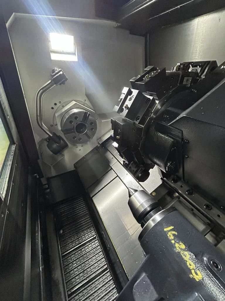
Miyano Citizen BNA-42DHY2 CNC Turning Center with Edge M542 Bar Feeder – Year 2013
| Manufacturer | Miyano |
|---|---|
| Model | BNA42DHY2 |
| Machine Type | 8-Axis CNC Turning Center with Sub Spindle |
| Year | 2013 |
| CNC Control | Fanuc Control |
| Bar Feed | Edge M542 Bar Feed |
| Spindle Configuration | Main spindle and sub spindle |
| Turret Configuration | Main live milling turret and sub turret |
| Axis Configuration | X / Y axis on main turret; X axis on sub spindle |
| Tooling | Includes tooling as shown, including one live tool |
| Documentation | Includes manuals and backup parameters on USB stick |
| Video | Available on request |
| Loading | Can be prepared and loaded at no charge |
| Section | Specification Item | Axis / Spindle / Unit | Unit | BNA-42DHY2 |
|---|---|---|---|---|
| A. Machining Capacity | Maximum Work Length | – | mm / inch | 100 mm / 3.937 in |
| A. Machining Capacity | Bar Capacity, Round | SP1 | mm / inch | Ø42 mm / 1.625 in |
| A. Machining Capacity | Bar Capacity, Round | SP2 | mm / inch | Ø34 mm / 1.312 in |
| B. Max. Slide Stroke | Turret Slide No.1 | X1-axis | mm / inch | 140 mm / 5.512 in |
| B. Max. Slide Stroke | Turret Slide No.1 | Z1-axis | mm / inch | 235 mm / 9.251 in |
| B. Max. Slide Stroke | Turret Slide No.1 | Y1-axis | mm / inch | 70 mm ±35 mm / 2.756 in ±1.378 in |
| B. Max. Slide Stroke | Spindle No.2 | X2-axis | mm / inch | 140 mm / 5.512 in |
| B. Max. Slide Stroke | Spindle No.2 | Z2-axis | mm / inch | 310 mm / 12.204 in |
| C. Spindle | Number of Spindle | – | – | 2 |
| C. Spindle | Spindle Speed Range | SP1 | min-1 | 60 – 6,000 |
| C. Spindle | Spindle Speed Range | SP2 | min-1 | 50 – 5,000 |
| C. Spindle | Inner Diameter of Draw Tube | SP1 | mm / inch | Ø43 mm / 1.692 in |
| C. Spindle | Inner Diameter of Draw Tube | SP2 | mm / inch | Ø30 mm / 1.181 in |
| C. Spindle | Chuck Cylinder | SP1 | – | SS1243-28 Hydraulic thru-hole chuck cylinder |
| C. Spindle | Chuck Cylinder | SP2 | – | SS1030-28 Hydraulic thru-hole chuck cylinder |
| C. Spindle | Collet Chuck | SP1 | – | Hardinge S20 |
| C. Spindle | Collet Chuck | SP2 | – | Same as BNC-34 type spring collet |
| C. Spindle | Power Chuck | SP1 | – | 5 in thru-hole chuck |
| C. Spindle | Power Chuck | SP2 | – | – |
| D. Spindle Index | Spindle Minimum Index Angle | SP1 | degree | 0.001 |
| D. Spindle Index | Spindle Minimum Index Angle | SP2 | degree | 0.001 |
| E. Tool Stand | Number of Tool Stands | – | – | 2 |
| E. Tool Stand | Form of Tool Stand | HD1 | – | 8ST. |
| E. Tool Stand | Form of Tool Stand | HD2 | – | 6ST. |
| E. Tool Stand | Distance Across Flat | HD1 | mm / inch | 200 mm / 7.874 in |
| E. Tool Stand | Distance Across Flat | HD2 | mm / inch | Direct axial mount |
| E. Tool Stand | Maximum Index Clearance | HD1 | mm / inch | Ø405 mm / 15.945 in |
| E. Tool Stand | Maximum Index Clearance | HD2 | mm / inch | Ø190 mm / 7.480 in |
| E. Tool Stand | Tool Shank Size | – | mm / inch | □20 mm / 0.787 in |
| E. Tool Stand | I.D Tool Hole Size | – | mm / inch | Ø25 mm / 0.984 in |
| F. Revolving Tool | Number of Revolving Tool Installed | – | – | Max. 8 |
| F. Revolving Tool | Spindle Speed Range | – | – | Infinitely variable |
| F. Revolving Tool | Revolving Tool Speed | – | min-1 | 50 – 5,000; Option: 10,000 |
| F. Revolving Tool | Machining Capacity | Drilling | mm | Max. Ø10 mm / 0.394 in |
| F. Revolving Tool | Machining Capacity | Tapping | mm | Max. M6 x 1 |
Machine Specifications / Feed, Motors, Power, Tank and Machine Size
| Section | Specification Item | Axis / Unit | Unit | BNA-42DHY2 |
|---|---|---|---|---|
| G. Slide Feed Speed | Rapid Traverse Rate | X1-axis | m/min | 20 m/min / 65.62 ft/min |
| G. Slide Feed Speed | Rapid Traverse Rate | Z1-axis | m/min | 20 m/min / 65.62 ft/min |
| G. Slide Feed Speed | Rapid Traverse Rate | Y1-axis | m/min | 20 m/min / 65.62 ft/min |
| G. Slide Feed Speed | Rapid Traverse Rate | X2-axis | m/min | 12 m/min / 39.37 ft/min |
| G. Slide Feed Speed | Rapid Traverse Rate | Z2-axis | m/min | 12 m/min / 39.37 ft/min |
| H. Slide Thrust Force | Slide Thrust Force | X1-axis | kN | 5 kN |
| H. Slide Thrust Force | Slide Thrust Force | Z1-axis | kN | 5 kN |
| H. Slide Thrust Force | Slide Thrust Force | Y1-axis | kN | 5 kN |
| H. Slide Thrust Force | Slide Thrust Force | X2-axis | kN | 4 kN |
| H. Slide Thrust Force | Slide Thrust Force | Z2-axis | kN | 5 kN |
| K. Electric Motor | Motor for Spindle | SP1 (Cs) | kW | 7.5 / 5.5 kW, 15 min / continuous |
| K. Electric Motor | Motor for Spindle | SP2 (Cs) | kW | 5.5 / 3.7 kW, 15 min / continuous |
| K. Electric Motor | Motor for Revolving Tool | – | kW | 2.8 / 1.0 kW |
| K. Electric Motor | Motor for Slide | X1-axis | kW | 1.2 kW |
| K. Electric Motor | Motor for Slide | Z1-axis | kW | 1.2 kW |
| K. Electric Motor | Motor for Slide | Y1-axis | kW | 1.2 kW |
| K. Electric Motor | Motor for Slide | X2-axis | kW | 0.75 kW |
| K. Electric Motor | Motor for Slide | Z2-axis | kW | 1.2 kW |
| K. Electric Motor | Motor for Turret Indexing | HD1 | kW | 0.75 kW |
| K. Electric Motor | Motor for Turret Indexing | HD2 | kW | 0.75 kW |
| K. Electric Motor | Motor for Hydraulic | – | kW | 0.75 kW |
| K. Electric Motor | Motor for Lubricating | – | kW | 0.004 kW |
| K. Electric Motor | Motor for Coolant Pump | – | kW | 0.18 kW |
| K. Electric Motor | Motor for High Pressure Coolant Pump | Option | kW | 1.0 / 0.6 kW, 60 / 50 Hz |
| L. NC Equipment | NC Equipment | – | – | FANUC 0i-TD |
| M. Source of Necessary Power | Power Supply | – | V / Hz | AC200 ±10%, 50 / 60 Hz ±1% |
| M. Source of Necessary Power | Power Supply Capacity | – | kVA | 30 kVA |
| M. Source of Necessary Power | Source of Air Pressure | – | MPa | 0.5 MPa |
| M. Source of Necessary Power | Equipment Side Fuse Capacity | – | A | 100 A |
| N. Tank Capacity | Hydraulic Oil Tank Capacity | – | L | 7 L / 1.85 gal, DAIKIN |
| N. Tank Capacity | Lubricating Oil Tank Capacity | – | L | 2 L / 0.53 gal |
| N. Tank Capacity | Coolant Tank Capacity | – | L | 165 L / 43.59 gal |
| P. Size of Machine | Height of Machine | – | mm | 1,700 mm / 66.93 in / 5.58 ft |
| P. Size of Machine | Floor Area | – | mm / inch | 2,240 x 1,450 mm / 88.189 x 57.48 in, length x width |
| P. Size of Machine | Machine Weight | – | kg | 3,900 kg / 8,598 lb |
NC Specifications / FANUC 0i-TD
| Name | Specification Item | Unit / Specification |
|---|---|---|
| Control Part | Control part | F.S. 0i-TD 2 system |
| Axial Control | Feed axis absolute position detection unit | X1, Z1, Y, X2, Z2 |
| Axial Control | Machine lock | – |
| Axial Control | Over travel | – |
| Axial Control | Stored stroke check | – |
| Axial Control | Chamfering ON/OFF | – |
| Axial Control | Backlash compensation | – |
| Axial Control | Minimum setting unit | 0.001 mm / 0.0001 inch / 0.001 deg |
| Axial Control | Cs outline control | – |
| Axial Control | Spindle synchronous control | – |
| Interpolation Functions | Positioning | G00 |
| Interpolation Functions | Linear interpolation and cornering | G01 |
| Interpolation Functions | Circular interpolation | G02, G03, Multi quadrant circular command |
| Interpolation Functions | Dwell | G04 |
| Interpolation Functions | Thread cutting | G32 |
| Interpolation Functions | Many article thread cutting | G33 |
| Interpolation Functions | Continuation thread cutting | – |
| Interpolation Functions | Polar coordinate interpolation | – |
| Interpolation Functions | Spindle rigid tap | – |
| Feed Rate | Rapid feed override | F0, 10, 20, 30, 40, 50, 60, 70, 80, 90, 100% |
| Feed Rate | Feed rate override | 0 – 150% |
| Feed Rate | Feed rate per minute / Feed rate | G98 / G99 |
| Feed Rate | Handle | x1, x10, x100 |
| Feed Rate | Reference point return | G28 |
| Feed Rate | Reference point return check | G27 |
| Feed Rate | Second return to reference point | G30 or G30P2 |
| Program Input Function | Tape code | EIA / ISO automatic identification |
| Program Input Function | Optional block skip | – |
| Program Input Function | Absolute command | X1, Z1, Y1, C1, X2, Z2, C2 |
| Program Input Function | Incremental command | U, W, V, H |
| Program Input Function | A decimal point input | – |
| Program Input Function | Programmable data input | G10 |
| Program Input Function | A diameter and radius specification | – |
| Program Input Function | G code system A | – |
| Program Input Function | Sub program call | 10 |
| Program Input Function | Custom macro B | – |
| Program Input Function | Single form fixed cycle | – |
| Program Input Function | Coordinate system setup | G50 |
| Program Input Function | Automatic coordinate system setup | – |
| Program Input Function | Coordinate system shift | – |
NC Specifications Continued / FANUC 0i-TD
| Name | Specification Item | Unit / Specification |
|---|---|---|
| Program Input Function | Coordinate system shift direct input | – |
| Program Input Function | Work coordinate system | From G52 to G59 |
| Program Input Function | Inch / metric change | – |
| Program Input Function | The circle radius R command | – |
| Program Input Function | Drawing size direct input | – |
| Program Input Function | Canned cycles for drilling | – |
| Program Input Function | Multiple repetitive cycles | – |
| Part Program Storage and Editing | Program storage capacity | 1 Mbyte / 2,560 m |
| Part Program Storage and Editing | Program storage capacity addition | 800 pieces |
| Part Program Storage and Editing | Program protection | – |
| Part Program Storage and Editing | Extended tape edit | – |
| Part Program Storage and Editing | Back land edit | – |
| S Function | Spindle function | S4 digit |
| S Function | Auxiliary function | M3 digit |
| S Function | System waiting function | – |
| S Function | Spindle serial output | – |
| S Function | Multi-spindle control | – |
| S Function | Spindle synchronous control | – |
| S Function | Constant surface speed control | G96 |
| T Function | Tool function | TOO△△, OO = Tool number and geometry, △△ = Wear offset number |
| T Function | Tool compensation number | HD1: 99 pieces, HD2: 20 pieces |
| T Function | Tool form and wear compensation | – |
| T Function | Tool position offset | – |
| T Function | The amount counter input of tool offset tool | – |
| T Function | Nose radius compensation | G40, G41, G42 |
| T Function | Tool life management | – |
| Operation Support Function | Automatic operation | – |
| Operation Support Function | MDI operation | – |
| Operation Support Function | Program number search | – |
| Operation Support Function | Sequence number search | – |
| Operation Support Function | Dry run | – |
| Operation Support Function | Single block | – |
| Operation Support Function | Optional stop | M01 |
| Operation Support Function | Jog feed | 1 – 1,260 mm/min / 0.039 – 49.61 in/min |
| Operation Support Function | Manual reference point return | – |
| Setup / Display Function | Machine alarm message display | – |
| Setup / Display Function | State display | – |
| Setup / Display Function | Clock functional | – |
| Setup / Display Function | Present position display | – |
| Setup / Display Function | Program display | – |
| Setup / Display Function | Alarm display | – |
| Setup / Display Function | Alarm history display | – |
| Setup / Display Function | Periodical maintenance screen | – |
| Setup / Display Function | Maintenance information screen | – |