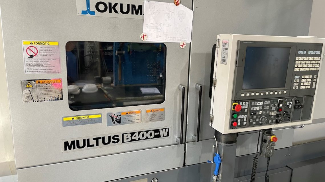
Industrial Insights: How to Spot Quality in Pre-Owned, Used, Secondhand, Surplus CNC Equipment Before Purchase Okuma Multus B400-W CNC Multi-Tasking Turn-Mill Center made in Japan
Here’s a detailed, industry-level guideline (checklist + warning signs) for assessing a pre-owned Okuma Multus B400-W (turn-mill / multitasking center, Japan-built) before purchase. I’ll first outline known spec features so you know “what to expect,” and then walk through what to inspect, test, and how to interpret findings. Use this as your on-site due diligence tool.
Known baseline specs & architecture (so you know what “good” looks like)
Before you inspect, you should collect or verify the as-built (or target) spec sheet. Below are typical specs for the Okuma Multus B400-W as known in industry listings and brochures:
| Spec | Typical Value / Range* |
|---|---|
| Machine type | Multitasking turn-mill (turning + milling + live tools + sub-spindle) |
| Number of axes | 7 (or sometimes up to 8, depending on configuration) |
| Swing / turning diameter | ~710 mm (≈ 27.95″) |
| Machining / working length (Z) | ~1,500 mm (≈ 60 in) |
| X travel | ~690 mm (≈ 27.17″) |
| Y travel (milling offset) | ± ~115 mm (i.e. ±4.5″) or ~230 mm total depending on spec sheet version |
| B-axis tilt / indexing | 225° indexing (e.g. –30° to +195°) with high resolution (0.001°) |
| Main spindle speed (turning) | ~38 – 3,800 rpm (some sources indicate up to 2,800 rpm in certain versions) |
| Milling / live-tool spindle speed | Up to ~10,000 rpm in many configurations |
| Tooling / turret | Capto C6 tooling for milling / live tools |
| Control / electronics | Okuma OSP-series (e.g. OSP-P or OSP-200L) |
| Weight / footprint | Very heavy (20+ tons), large footprint; e.g. “machine weight ~34,000 lbs” in one listing. |
* These are typical values, but specific units may differ based on configuration, options, or region.
Because the Multus is a complex multitasking machine (turning + milling + live tooling + B-axis + sub spindle) it has many more potential failure modes than a simple 3-axis VMC or lathe. That makes the inspection even more critical.
Pre-visit preparation
Before showing up on site, do the following to maximize your inspection effectiveness:
- Obtain documentation & service history
- Maintenance logs, repairs, parts replaced, alignment checks, rebuilds, spindle history.
- Machine hours (turning hours, milling hours) if available (not just “on time”).
- Control backups, parameter files, calibration records, wiring diagrams, parts list.
- Any history of crashes, overloads, or collisions.
- Request a demonstration via video / remote control
- Jogging axes, running the milling spindle, tool change operations, sub-spindle transfer, simultaneous motion.
- If possible, ask the seller to perform a “test cut” or run a known part program while you watch.
- Bring inspection tools & reference hardware
- Dial indicators, test bars, gauge blocks, edge finders, quality reference bars, maybe a portable vibration meter or stethoscope.
- Thermal probe or thermometer to check temperature gradients.
- Your own known “reference part” or master gauge, if feasible.
- Arrange for technical support / expert
- If you’re not specialized in Okuma or multitasking machines, bring someone who is (mechanical, CNC, controls).
- Having someone who can interpret control alarms or servo feedback during inspection is extremely helpful.
- Check spare parts & local support
- Are critical spares (spindle bearings, servo modules, B-axis gearboxes, control boards) available in your region (Turkey)?
- Are there service firms locally who know how to service Okuma OSP controls and multitasking machines?
- Prepare logistics / installation plan
- Because this machine is massive and heavy, ensure you know crane, foundation, floor load, power, cooling, utility hookups, transport paths, etc.
On-site inspection & testing checklist
Below is a detailed checklist and what to look (and listen) for. For each system, I include “good sign,” “acceptable tolerance,” and “red flag / warning.”
| System / Subsystem | Inspection / Test | Good Signs / Acceptable | Red Flags / Warning Indicators |
|---|---|---|---|
| Frame, castings, structural | Visually inspect for cracks, repaired welds, distortion, corrosion; check alignment of base surfaces | No cracks, no obvious repair welds, minimal rust, surfaces flat | Weld repairs, cracked castings, twisted base, obvious misalignment |
| Way covers, bellows, guards | Traverse axes (X, Y, Z, W, B) manually or via slow jog; examine covers for contact, deformation | Covers move freely, no dragging, no holes, no sagging | Bellows torn, sagging, cover hitting tool or table, debris stuck underneath |
| Ball screws / linear guides / slideways | Jog axis, stop and reverse to check backlash, feel for smoothness, measure with dial indicator | Low backlash (within manufacturer spec), smooth motion across full travel | Excessive backlash, “dead spots,” binding in portions, vibration or chirping noise |
| Rotary / B-axis / tilt mechanism | Index B-axis, move through full tilt range under load, check for backlash or play in B-axis gear train | Precise indexing, no slop, smooth motion | Backlash in B-axis, jitter, binding near extremes, gear tooth damage |
| Sub-spindle (W axis) | Transfer a part from main to sub, test tight coupling, rotate sub spindle, run motion | Clean transfer, tight engagement, stable rotation without wobble | Loose coupling, difficulty in part transfer, vibration in sub spindle, poor alignment |
| Main spindle (turning) | Run through speed range (low to high), measure runout with test bar, listen for bearings noise, check temperature | Quiet across speeds, runout in a few microns, stable temperature | Grinding, knocking, excessive vibration, high heat, wobble in test bar |
| Milling / live tool spindle | Engage milling spindle, test in axial and radial motion, check live tool speed and stability | Clean operation, stable rpm up to spec, no chatter | Tool chatter, excessive vibration, spindle noise, failure at high rpm |
| Tool changers / turret / ATC | Cycle tool changes, index turret, test quick change, check tool retention, alignment | Smooth indexing, no misses, tight retention, repeatable, no error alarms | Tool drop, mis-index, slow cycles, worn pockets, collision marks |
| Servo drives / motors / amplifiers | Cycle each axis at various speeds, full rapid traverse, direction reversal, no drive faults | Stable motion, no alarms, no thermal stress, responsive drives | Drive trips, overheating, axis fault alarms, jittery motion, loss of axis control |
| CNC control / electronics cabinet | Open cabinet, inspect wiring, cleanliness, fan operation, dust, burnt areas; power on and check control health, I/O integrity, alarm logs | Neat wiring, functioning fans, no burns, control boots cleanly, able to access parameters, I/O OK | Burnt terminals, broken wires, fan failure, error codes on boot, I/O missing signals |
| Cooling / lubrication systems | Check conditions of coolant (cleanliness, pH, contamination), pumps, filters, piping; check automatic lube system for axes | Clean coolant, functioning pumps, no leaks, good lubrication flow | Clogged filters, leaks, pump failure, poor lubrication, fluid contamination |
| Chip / debris handling | Run chip conveyors, chip augers, test that chips are removed cleanly, no buildup | Chips flow freely, conveyors run, no jams | Chips stuck or jammed, conveyor motor faults, pile-ups, broken conveyors |
| Thermal stability / drift | Operate machine for extended time, then re-measure critical dimensions to see drift | Minimal drift after warm-up, stable readings over repeated cycles | Dimensional drift, variation between cold and hot, readjustments required mid-cut |
| Accuracy / repeatability tests | Use gauge blocks, test bars, master parts or CMM to verify positioning at multiple points and repeated cycles | Consistent within manufacturer tolerances (a few microns) | Inconsistent readings, drift, nonlinearity across envelope, variation beyond spec |
| Full-load / cutting test | If possible, run a real part with typical cuts, watch for chatter, torque overloads, surface finish issues | Stable performance, no alarms, good finish, accurate parts | Chatter, tool breakage, unstable paths, servo overloads, finish defects |
| Software / control features | Test all features (e.g. collision avoidance, thermal compensation, synchronized motion, B-axis functions, macro routines) | All options functional, collision avoidance works, motion compensation active | Disabled options, missing licenses, errors in kinematics, control crashes under advanced motion |
| Documentation & spare parts | Confirm presence of manuals, wiring diagrams, parameter backups, parts lists; check availability of spares | Full documentation, ability to source key spare parts locally | Missing documentation, no spare parts catalog, obscure or custom mods without documentation |
Interpreting results & decision criteria
Given the complexity of a multitasking machine like the Multus B400-W, here’s how to interpret what you find:
- Fixable vs. fatal defects
Minor wear (covers, slight backlash, cosmetic damage) is normal. But major issues—spindle bearing failure, B-axis gear wear, control board failures, severe misalignment—are very expensive to repair. - Cost of remediation vs. discount
Use your findings to negotiate. The discount should more than cover parts, labor, downtime, and risk. - Spare parts & expertise in your region
If key parts (B-axis gearboxes, Okuma OSP control boards, spindles) are not available locally, even a “good” machine may become a liability. - Residual useful life & maintenance outlook
If the machine has high working hours and many subsystems nearing end-of-life, you might be buying a “time bomb.” - Control / software obsolescence
A mechanically sound machine with an obsolete or unsupported control is risky. Ensure the OSP is modern or upgradeable. - Warranty / acceptance period
Negotiate a post-delivery acceptance period (e.g. 30–90 days) during which you fully test under workload, before final acceptance. - Transport / reinstallation risk
Large precision machines tend to shift during transport. Always plan re-leveling, re-calibration, checking alignment after installation. - Use a weighted scoring approach
Assign weights to subsystems (e.g. spindle, B-axis, control electronics more critical) and score them. A machine passing in low-weight areas but failing in critical areas should be rejected or heavily discounted.